ZYXEL COMMUNICATIONS CORPORATION
U-336S
|
Card Type |
Modem (synchronous/asynchronous), fax |
|
Chip Set |
Unidentified |
|
Maximum Modem Rate |
33.6Kbps |
|
Maximum Fax Rate |
14.4Kbps |
|
Data Modulation Protocol |
Bell 103/212A ITU-T V.21, V.22, V.22bis, V.32, V.32bis, V.34 |
|
Fax Modulation Protocol |
ITU-T V.17, V.27ter, V.29 |
|
Error Correction/Compression |
MNP5, V.42, V.42bis |
|
Fax Class |
Class I & II |
|
Data Bus |
External |
|
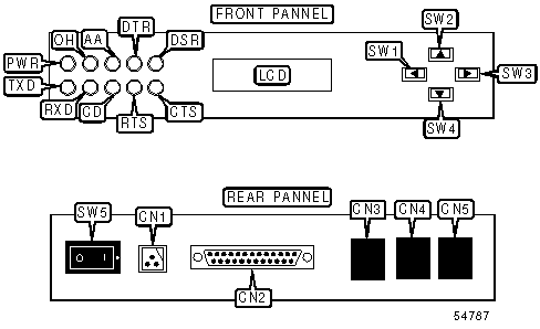
CONNECTIONS | ||||||
|
Function |
Label |
Function |
Label | |||
|
DC power |
CN1 |
Scroll left |
SW1 | |||
|
25-pin serial port |
CN2 |
Scroll up |
SW2 | |||
|
Line in |
CN3 |
Scroll right |
SW3 | |||
|
Line out |
CN4 |
Scroll down |
SW4 | |||
|
Leased line |
CN5 |
Power switch |
SW5 | |||
|
DIAGNOSTIC LED(S) | |||
|
LED |
Color |
Status |
Condition |
|
PWR |
Unidentified |
On |
Power is on |
|
PWR |
Unidentified |
Off |
Power is off |
|
TXD |
Unidentified |
On |
Modem is transmitting data |
|
TXD |
Unidentified |
Off |
Modem is not transmitting data |
|
RXD |
Unidentified |
On |
Modem is receiving data |
|
RXD |
Unidentified |
Off |
Modem is not receiving data |
|
CD |
Unidentified |
On |
Carrier signal detected |
|
CD |
Unidentified |
Off |
Carrier signal not detected |
|
DTR |
Unidentified |
On |
Computer is ready to send/receive data |
|
DTR |
Unidentified |
Off |
Computer is not ready to send/receive data |
|
DSR |
Unidentified |
On |
Modem is ready to send/receive data |
|
DSR |
Unidentified |
Off |
Modem is not ready to send/receive data |
|
RTS |
Unidentified |
On |
DTE requesting to send data for transmission |
|
RTS |
Unidentified |
Off |
DTE not requesting to send data for transmission |
|
CTS |
Unidentified |
On |
Modem clear to send |
|
CTS |
Unidentified |
Off |
Modem not clear to send |
|
OH |
Unidentified |
On |
Modem is off-hook |
|
OH |
Unidentified |
Off |
Modem is on-hook |
|
AA |
Unidentified |
On |
Modem is in auto-answer mode |
|
AA |
Unidentified |
Off |
Modem is not in auto-answer mode |
|
AA |
Unidentified |
Blinking |
Modem is ringing; In error control mode, indicates that modem is retransmitting |
|
SUPPORTED COMMAND SET |
|
Basic AT Commands |
|
AT, ‘+++’, A/ |
|
A, B, E, H, M, O, T, V |
|
&C, &F, &J, &M, &R, &T, &X, &Z |
|
S Registers |
|
S0, S1, S2, S3, S4, S5, S6, S7, S8, S9, S10, S11, S16 |
Proprietary AT Command Set
|
BREAK HANDLING | |
|
Type: |
Configuration |
|
Format: |
AT [cmds] &Yn [cmds] |
|
Description: |
Break handling |
|
Command |
Function |
|
í &Y0 |
Break sent to remote modem immediately |
|
&Y1 |
Break sent to remote modem and buffer cleared |
|
&Y2 |
Send break with transmitted data |
|
CONFIGURATION PROFILES | |
|
Type: |
Immediate |
|
Format: |
AT [cmds] &Vn [cmds] |
|
Description: |
Displays active and stored configuration profiles |
|
Command |
Function |
|
&V0 |
View current active settings |
|
&V1 |
View user profile 1 |
|
&V2 |
View user profile 2 |
|
&V3 |
View user profile 3 |
|
&V4 |
View user profile 4 |
|
&V5 |
View factory default settings |
|
DATA RATE | |
|
Type: |
Configuration |
|
Format: |
AT [cmds] &Bn [cmds] |
|
Description: |
Controls the DTE rate |
|
Command |
Function |
|
í &B0 |
Serial speed follows connect speed |
|
&B1 |
Serial speed locked |
|
DATA SET READY (DSR) | |
|
Type: |
Configuration |
|
Format: |
AT [cmds] &Sn [cmds] |
|
Description: |
Selects DSR options |
|
Command |
Function |
|
í &S0 |
DSR forced high |
|
&S1 |
DSR according to CCITT (ITU-TSS) |
|
DATA TERMINAL READY (DTR) | |
|
Type: |
Configuration |
|
Format: |
AT [cmds] &Dn [cmds] |
|
Description: |
Selects modem response to DTR |
Note: The action each variant of &D causes depends on the setting of &Q | |
|
Command |
Function |
|
í &D0 |
Modem does not respond to DTR |
|
&D1 |
Modem goes to command mode after DTR goes is off |
|
&D2 |
Modem goes to command mode and disconnects (hangs up) after DTR goes off; Auto-Answer is disabled. |
|
&D3 |
Modem is initialized after DTR goes off |
|
DIAL | |
|
Type: |
Immediate |
|
Format: |
AT [cmds] D<#> [cmds] |
|
Description: |
Dials telephone number according to any modifiers included in the string |
|
Note: |
Any combination of modifiers can be used to produce the desired dial functions in sequence. |
|
Command |
Function |
|
DP |
Pulse dialing enabled |
|
DR |
Answer mode enabled; originate mode disabled following handshake initiation. |
|
DS=n |
Dial stored telephone number n |
|
DT |
Tone dialing enabled/Pulse dialing disabled |
|
DW |
Dialing resumed following dial tone detection |
|
D, |
Dialing paused for amount of time specified in S8 register |
|
D! |
Flash function initiated. Modem commanded to go off-hook for specified time before returning on-hook. |
|
D@ |
Wait for Quite Answer function enabled. Modem waits until a "quiet answer," a ring-back signal followed by silence up to the time specified in S7, is received prior to executing the rest of the dial string. |
|
DL |
Repeat last ATD command |
|
D; |
Modem returned to idle state after dialing. The semicolon can only be placed at the end of the dial command. |
|
DOWNLOAD FIRMWARE | |
|
Type: |
Configuration |
|
Format: |
AT [cmds] UPX [cmds] |
|
Description: |
Download firmware to the Flash EPROM using Xmodem protocol |
|
ERROR CONTROL | |
|
Type: |
Configuration |
|
Format: |
AT [cmds] &Kn [cmds] |
|
Description: |
Enables error control options |
|
Command |
Function |
|
&K0 |
Error control disabled |
|
&K1 |
Error control enabled |
|
&K2 |
MNP4 and MNP5 error control enabled |
|
í &K3 |
V.42 and MNP4 error control enabled |
|
&K4 |
V.42 and V.42bis error control enabled |
|
GUARD TONE | |
|
Type: |
Configuration |
|
Format: |
AT [cmds] &Gn [cmds] |
|
Description: |
Commands the modem to transmit a guard tone in V.22/V.22bis |
Note: Used primarily for international data transmission | |
|
Command |
Function |
|
í &G0 |
Guard tone disabled |
|
&G2 |
1800Hz guard tone enabled |
|
HELP | |
|
Type: |
Immediate |
|
Format: |
AT [cmds] $ [cmds] |
|
Description: |
Display help screen |
|
Command |
Function |
|
$ |
Basic command summary |
|
&$ |
Extended command summary |
|
*$ |
Extended command summary |
|
LINE TYPE | |
|
Type: |
Configuration |
|
Format: |
AT [cmds] &Ln [cmds] |
|
Description: |
Selects line type |
|
Command |
Line Type |
|
í &L0 |
Switched line (PSTN/Dial-up) |
|
&L1 |
2W leased-line |
|
&L2 |
4W leased-line |
|
RE-EXECUTE | |
|
Type: |
Immediate |
|
Format: |
A> <CR> |
|
Description: |
Re-executes the last command once or the last call up to 9 times. |
Note: Do not precede this command with AT. This version of the escape sequence is used in non-Hayes modems. | |
|
REPORT INFORMATION | |
|
Type: |
Immediate |
|
Format: |
AT [cmds] In [cmds] |
|
Description: |
Displays information requested |
|
Command |
Function |
|
I0 |
Reports modem model and speed |
|
I1 |
Reports ROM checksum |
|
I2 |
Report modem link status |
|
I12 |
Report physical layer status |
|
RESULT CODES | |
|
Type: |
Configuration |
|
Format: |
AT [cmds] Qn [cmds] |
|
Description: |
Enables modem to send result codes to the DTE |
|
Command |
Function |
|
í Q0 |
Result code sending enabled |
|
Q1 |
Result code sending disabled |
|
Q2 |
Modem returns result code but quiet after answering on a RING |
|
RING VOLUME | |
|
Type: |
Configuration |
|
Format: |
AT [cmds] Nn [cmds] |
|
Default: |
5 |
|
Range: |
0-7 |
|
Description: |
Ring volume control. ‘NO’ will disable the audio ring function |
|
MODEM LINK MODE | |
|
Type: |
Configuration |
|
Format: |
AT [cmds] &Nn [cmds] |
|
Description: |
Modem link mode options |
|
Command |
Mode |
|
í &N0 |
Multi-Auto, auto negotiate highest possible link rate |
|
&N1 |
V.33 14400/12000 |
|
&N2 |
V.33 12000 |
|
&N3 |
V.32 9600T/9600/7200T/4800 |
|
&N4 |
V.32 9600/7200/4800 |
|
&N5 |
V.32 4800 |
|
&N12 |
V.23 1200/75 |
|
&N13 |
V.23 600/75 |
|
&N14 |
V.22bis 2400/1200 |
|
&N15 |
V.22 1200 |
|
&N16 |
V.21 300 |
|
&N17 |
V.32bis 14400/12000/9600/7200/4800 |
|
&N18 |
V.32bis 12000/9600/7200/4800 |
|
&N19 |
V.32bis 7200/4800 |
|
&N24 |
BELL 212A 1200 |
|
&N25 |
BELL 103 300 |
|
&N32 |
G3 Fax V.17/V.29/V.27ter 14400/12000/9600/7200/4800/2400 |
|
&N34 |
ZyXEL 19200 |
|
&N35 |
ZyXEL 16800 |
|
&N36 |
ZyXEL 14400 |
|
&N37 |
ZyXEL 12000 |
|
&N38 |
ZyXEL 9600 |
|
&N39 |
ZyXEL 7200 |
|
&N42 |
CELL 14400 |
|
&N43 |
CELL 12000 |
|
&N44 |
CELL 9600 |
|
&N45 |
CELL 7200 |
|
&N46 |
CELL 4800T |
|
&N62 |
V.34 28800 |
|
&N63 |
V.34 26400 |
|
&N64 |
V.34 24000 |
|
&N65 |
V.34 21600 |
|
&N66 |
V.34 19200 |
|
&N67 |
V.34 16800 |
|
&N68 |
V.34 14400 |
|
&N69 |
V.34 12000 |
|
&N70 |
V.34 9600 |
|
&N71 |
V.34 7200 |
|
&N72 |
V.34 4800 |
|
&N73 |
V.34 2400 |
|
PULSE DIALING RATIO | |
|
Type: |
Configuration |
|
Format: |
AT [cmds] &Pn [cmds] |
|
Description: |
Selects pulse dial make/break ratio |
|
Command |
Function |
|
í &P0 |
39/61ms at 10pps (North America) |
|
&P1 |
33/67ms at 10pps (Europe) |
|
SELECT CALL PROGRESS RESULT CODES | |
|
Type: |
Immediate |
|
Format: |
AT [cmds] Xn [cmds] |
|
Description: |
Enables selection of tone detection and associated result code format options |
|
Command |
Function |
|
X0 |
Busy and dial tone detection disabled; result codes 0 - 4 enabled. |
|
X1 |
Busy and dial tone detection disabled; result codes 0 - 5 & 10 enabled. |
|
X2 |
Busy tone detection disabled, dial tone detection enabled; result codes 0 - 6 & 10 enabled. |
|
X3 |
Busy tone detection enabled, dial tone detection disabled; result codes 0 - 5, 7 & 10 enabled. |
|
X4 |
Busy and dial tone detection enabled; result codes 0 - 7 & 10 enabled. |
|
X5 |
Busy and dial tone detection enabled: result codes 0 - 7 & 10 enabled. Reports DTE speed, all CARRIER & PROTOCOL extended result codes enabled |
|
X6 |
Busy and dial tone detection enabled; result codes 0 - 7 & 10 enabled. Reports DCE speed, all extended result codes disabled |
|
X7 |
Busy and dial tone detection enabled; result codes 0 - 7 & 10 enabled. Reports DCE speed, all CARRIER & PROTOCOL extended result codes enabled |
|
SOFT RESET | |
|
Type: |
Immediate |
|
Format: |
AT [cmds] Zn [cmds] |
|
Description: |
Restores modem profiles previously saved in non-volatile RAM using the &W command. |
|
Command |
Function |
|
Z0 |
Restore setting 0 |
|
Z1 |
Restore setting 1 |
|
Z2 |
Restore setting 2 |
|
Z3 |
Restore setting 3 |
|
Z4 |
Restore factory settings |
|
SPEAKER VOLUME | |
|
Type: |
Configuration |
|
Format: |
AT [cmds] Ln [cmds] |
|
Default: |
4 |
|
Range: |
0-7 |
|
Description: |
Controls speaker volume |
|
STORE ACTIVE PROFILE | |
|
Type: |
Configuration |
|
Format: |
AT [cmds] &Wn [cmds] |
|
Description: |
Writes the values for the user profile n into the non-volatile RAM |
|
TERMINATE CONNECTION | |
|
Type: |
Immediate |
|
Format: |
<any key> <CR> |
|
Description: |
Terminate current connection attempt when enter in handshaking state. |
Note: Do not precede this command with AT. This version of the escape sequence is used in non-Hayes modems. | |
Extended AT Command Set
|
AUTO HANDSHAKE MODE | |
|
Type: |
Configuration |
|
Format: |
AT [cmds] *Mn [cmds] |
|
Description: |
Leased line auto-handshake mode selection |
|
Command |
Function |
|
*M0 |
Set to Originate mode |
|
*M1 |
Set to Answer mode |
|
CALLER ID | |
|
Type: |
Configuration |
|
Format: |
AT [cmds] *T [cmds] |
|
Description: |
Recall the last CND (Caller ID) information |
|
CHARACTER LENGTH | |
|
Type: |
Configuration |
|
Format: |
AT [cmds] *Cn [cmds] |
|
Description: |
Controls the character length, including start, stop and parity bit |
|
Command |
Function |
|
*C0 |
10-bit character length |
|
*C1 |
11-bit character length |
|
*C2 |
9-bit character length |
|
*C3 |
8-bit character length |
|
COMMAND SET | |
|
Type: |
Configuration |
|
Format: |
AT [cmds] *In [cmds] |
|
Description: |
Command set selection |
|
Command |
Function |
|
*I0 |
AT command set |
|
*I1 |
V.25bis command set |
|
*I2 |
Dumb mode |
|
CONFIGURATION PROFILE | |
|
Type: |
Configuration |
|
Format: |
AT [cmds] *Wab [cmds] |
|
Description: |
Write local configuration profile a to remote user profile b and reset modem from profile b |
|
Command |
Function |
|
a=0 |
Assign local user profile 0 to "a" |
|
a=1 |
Assign local user profile 1 to "a" |
|
a=2 |
Assign local user profile 2 to "a" |
|
a=3 |
Assign local user profile 3 to "a" |
|
b=0 |
Assign local user profile 0 to "b" |
|
b=0 |
Assign local user profile 1 to "b" |
|
b=0 |
Assign local user profile 2 to "b" |
|
b=0 |
Assign local user profile 3 to "b" |
|
a=4 |
Local active configuration |
|
a=5 |
Local factory default configuration |
|
DEFAULT DIAL POINTER | |
|
Type: |
Configuration |
|
Format: |
AT [cmds] *Dn [cmds] |
|
Range: |
0-49 |
|
Description: |
Set default dial pointer at telephone directory location n |
|
LINE QUALITY | |
|
Type: |
Configuration |
|
Format: |
AT [cmds] *Qn [cmds] |
|
Description: |
Action taken when line quality changes |
|
Command |
Function |
|
*Q0 |
No action to poor signal quality |
|
*Q1 |
Retrain action taken in signal quality is poor |
|
*Q2 |
Adaptive rate, automatic fall-back or forward |
|
*Q3 |
Disconnect if signal quality is poor |
|
MODEM ERROR CONTROL NEGOTIATION | |
|
Type: |
Configuration |
|
Format: |
AT [cmds] *En [cmds] |
|
Description: |
Modem error control negotiation |
|
Command |
Function |
|
*E0 |
If error control negotiation fails, keep the non-error control connection |
|
*E1 |
If error control negotiation fails, disconnect the call (hang-up) |
|
PASSWORD TABLE | |
|
Type: |
Immediate |
|
Format: |
AT [cmds] *V [cmds] |
|
Description: |
View the Password table |
|
REMOTE CONFIGURATION | |
|
Type: |
Configuration |
|
Format: |
AT [cmds] *Fn [cmds] |
|
Description: |
Remoter configuration enable |
|
Command |
Function |
|
*F0 |
Deny remote configuration |
|
*F1 |
Accept remote configuration |
|
REMOTE PROFILE | |
|
Type: |
Configuration |
|
Format: |
AT [cmds] *Rab [cmds] |
|
Description: |
Read the remote profile "b" to local user profile "a" |
|
Options |
Function |
|
a=0 |
Assign local user profile 0 to "a" |
|
a=1 |
Assign local user profile 1 to "a" |
|
a=2 |
Assign local user profile 2 to "a" |
|
a=3 |
Assign local user profile 3 to "a" |
|
b=0 |
Assign local user profile 0 to "b" |
|
b=0 |
Assign local user profile 1 to "b" |
|
b=0 |
Assign local user profile 2 to "b" |
|
b=0 |
Assign local user profile 3 to "b" |
|
b=4 |
Remote active configuration |
|
b=5 |
Remote factory default configuration |
|
SECURITY FUNCTION | |
|
Type: |
Configuration |
|
Format: |
AT [cmds] *Gn [cmds] |
|
Description: |
Security function selection |
|
Command |
Function |
|
*G0 |
Disable security functions |
|
*G1 |
Enable type 1 security, with password check |
|
*G2 |
Enable type 1 security, with password check and call back |
|
*G3 |
Enable type 2 security, with password check |
|
*G4 |
Enable type 2 security, with password check and call back |
|
*G5 |
Enable type 2 security, with password check and call back, remote user enters the call back number. |
|
SUPERVISOR PASSWORD | |
|
Type: |
Configuration |
|
Format: |
AT [cmds] *HS [cmds] |
|
Description: |
Modify supervisory password (default: "ZyXEL") |
|
TRANSMISSION POWER LEVEL | |
|
Type: |
Configuration |
|
Format: |
AT [cmds] *Pn [cmds] |
|
Default: |
9 |
|
Range: |
0-15 |
|
Description: |
Set leased line transmission power level |
|
USER PASSWORD | |
|
Type: |
Configuration |
|
Format: |
AT [cmds] *Hn [cmds] |
|
Range: |
0-49 |
|
Description: |
Modify user password table at location n |
S(status) -REGISTERS
|
BIT-MAPPED REGISTER S13 | |
|
Format: |
AT [cmds] S13=n [cmds] |
|
Default: |
170 |
|
Unit: |
Bit-mapped |
|
Description: |
Capture modem information |
|
BIT-MAPPED REGISTER S14 | ||
|
Format: |
AT [cmds] S14=n [cmds] | |
|
Default: |
170 | |
|
Unit: |
Bit-mapped | |
|
Description: |
Controls auto-handshake | |
|
Bit |
Value |
Function |
|
0 |
í 01 |
Modem auto-handshake on Originate mode Modem auto-handshake on Answer mode |
|
1 |
0 í 1 |
Grant remote Digital Loop-back test request Deny remote Digital Loop-back test request |
|
3,2 |
í 01 8 |
Dial-up line 2-wire leased line 4-wire leased line |
|
5,4 |
í 016 32 |
Internal clock External clock Remote clock |
|
7,6 |
í 064 128 192 |
Asynchronous data with buffering Asynchronous command, synchronous data Direct asynchronous, no data buffering Synchronous |
|
BIT_MAPPED REGISTER S15 | ||
|
Type: |
Register | |
|
Format: |
AT [cmds] S15=n [cmds] | |
|
Description: |
Controls parity | |
|
Bit |
Value |
Function |
|
0,1 |
í 01 2 |
Even parity Odd parity No parity |
|
2 |
í 04 |
1 stop bit 2 stop bits |
|
4,3 |
í 08 16 24 |
10 bit character length 11 bit character length 9 bit character length 8 bit character length |
|
7-5 |
í 032 64 96 128 |
Profile 0 as active settings after power on Profile 1 as active settings after power on Profile 2 as active settings after power on Profile 3 as active settings after power on Factory default as active settings after power on |
|
BIT-MAPPED REGISTER S17 | ||
|
Type: |
Register | |
|
Format: |
AT [cmds] S17=n [cmds] | |
|
Unit: |
Bit-mapped | |
|
Description: |
Controls dialing | |
|
Bit |
Value |
Function |
|
0 |
0 |
Disable secondary channel |
|
4-1 |
í 0-30 |
Set leased line transmit power level from 0 to 15 dBn. |
|
5 |
í 032 |
Normal dial Reverse dial, go on-line in answer mode |
|
7,6 |
í 064 128 |
AT command set V.25bis command set Dumb mode |
|
BAUD RATE | ||
|
Type: |
Register | |
|
Format |
AT [cmds] S18=n [cmds] | |
|
Description: |
Force modem to fix baud rate when answering | |
|
Bit |
Value |
Function |
|
0 |
0 |
Disable fixed baud rate |
|
1-46 |
1-2E |
Enable baud rate to be fixed when answering. Baud rate value settings (n) the same as S20 |
|
MODEM CONNECTION MODE | ||
|
Type: |
Register | |
|
Format |
AT [cmds] S19=n [cmds] | |
|
Description: |
MODEM CONNECTION MODE | |
Note: S18=0 disables the timer and allows an indefinite duration. | ||
|
Value |
Function | |
|
0-73 |
Setting value as ‘AT&Nn’ command | |
|
BIT-MAPPED REGISTER S20 | |
|
Format |
AT [cmds] S20=n [cmds] |
|
Default: |
Unidentified |
|
Unit: |
Bit-mapped |
|
Description: |
DTE speed (bps). Auto detect from AT Command |
|
Value |
Function |
|
S20=0 |
230400bps |
|
S20=1 |
115200bps |
|
S20=2 |
76800bps |
|
S20=3 |
57600bps |
|
S20=4 |
38400bps |
|
S20=5 |
19200bps |
|
S20=6 |
16800bps |
|
S20=7 |
14400bps |
|
S20=8 |
12000bps |
|
S20=9 |
9600bps |
|
S20=10 |
7200bps |
|
S20=11 |
4800bps |
|
S20=12 |
2400bps |
|
S20=13 |
1200bps |
|
S20=14 |
460800bps |
|
S20=15 |
300bps |
|
S20=16 |
307200bps |
|
S20=17 |
153600bps |
|
S20=18 |
102400bps |
|
S20=20 |
61440bps |
|
S20=21 |
51200bps |
|
S20=22 |
62400bps |
|
S20=24 |
124800bps |
|
S20=25 |
62400bps |
|
S20=26 |
41600bps |
|
S20=27 |
31200bps |
|
S20=28 |
24960bps |
|
S20=29 |
20800bps |
|
S20=46 |
92160bps |
|
BIT-MAPPED REGISTER S21 | ||
|
Format |
AT [cmds] S21=n [cmds] | |
|
Default: |
Unidentified | |
|
Unit: |
Bit-mapped | |
|
Description: |
Auto speed detection | |
|
Bit |
Value |
Function |
|
0 |
0 1 |
Maintain non-error control connection when modem error control handshake fails Drop connection when modem error control handshake fails |
|
1-2 |
0 2 4 6 |
Speaker always off Speaker on until carrier is detected Speaker always on Speaker on after last digit is dialed out until carrier is detected |
|
3 |
0 8 |
DSR always on According to CCITT |
|
4 |
0 16 |
CD always on CD tracks presence of data carrier |
|
5 |
0 |
CTS follows RTS in synchronous mode. Response delay set in S26. |
|
32 |
Ignore RTS (CTS always on) in synchronous mode. | |
|
6-7 |
0 64 128 192 |
Assume DTR always on 108.1 DTR off-on transition causes dial of the default number 108.2 Data Terminal Ready. DTR off causes the modem to hang up and return to command mode 108.2 DTR off causes the modem to hang up and reset the modem to profile #0 after DTR dropped |
|
BIT-MAPPED REGISTER S23 | ||
|
Format |
AT [cmds] S23=n [cmds] | |
|
Default: |
Unidentified | |
|
Unit: |
Bit-mapped | |
|
Description: |
Bit mapped register | |
|
Bit |
Value |
Function |
|
0 |
0 1 |
Command echo disabled Command echo enabled |
|
1 |
0 2 |
Tone dial Tone dial |
|
2 |
0 4 |
Pulse dial make/break ratio = 39% / 61% Pulse dial make/break ratio = 33% / 67% |
|
3-5 |
0 8 16 24 32 40 48 56 |
ATX0 ATX1 ATX2 ATX3 ATX4 ATX5 ATX5, error control result code enabled ATX6, error control result code enabled |
|
6 |
0 64 |
Display result code in verbose format (see S35.7) Display result code in verbose format |
|
7 |
0 128 |
Modem returns result state Modem does not return result code |
|
BIT MAPPED REGISTER S24 | ||
|
Type: |
Register | |
|
Format |
AT [cmds] S24=n [cmds] | |
|
Default: |
Unidentified | |
|
Unit: |
Unidentified | |
|
Description: |
Bit mapped register | |
|
Bit |
Value |
Function |
|
2-0 |
0-7 |
Ring volume control |
|
6-4 |
16-112 |
Speaker volume control |
|
DTR TIME DELAY | |
|
Type: |
Register |
|
Format |
AT [cmds] S25=n [cmds] |
|
Default: |
0 |
|
Range: |
Unidentified |
|
Unit: |
.1 second |
|
Description: |
Specify the time delay that DTR signal needs to be off before it will be recognizedIf S25=0, the delay time is set to 4ms. |
|
RTS/CTS DELAY | |
|
Type: |
Register |
|
Format |
AT [cmds] S26=n [cmds] |
|
Default: |
0 |
|
Range: |
0 - 255 |
|
Unit: |
.1 second |
|
Description: |
Set the delay, in 10ms units between the RTS and modem’s CTS response in synchronous mode. |
|
BIT-MAPPED REGISTER S27 | |||
|
Format |
AT [cmds] S27=n [cmds] | ||
|
Default: |
Unidentified | ||
|
Unit: |
Bit-mapped | ||
|
Description: |
Bit mapped register | ||
|
Bit |
Value |
Function | |
|
0-2 |
0 1 2 3 4 |
No error control MNP4 and MNP3 error control MNP4 and MNP5 error control V.42 and MNP4 error control V.42 and V.42bis error control | |
|
3-5 |
0 24 32 40 |
Flow control disabled Hardware (RTS/CTS) flow control Software (XON/XOFF) flow control Reserved | |
|
6-7 |
0 64 128 192 |
No response to poor signal quality Retrain action taken if signal quality *Q1 is poor Adaptive rate (auto fall back/forward) when signal quality changes Disconnect when signal quality is poor | |
|
BIT-MAPPED REGISTER S28 | ||
|
Format |
AT [cmds] S28=n [cmds] | |
|
Default: |
unidentified | |
|
Unit: |
Bit-mapped | |
|
Description: |
Bit mapped register | |
|
Bit |
Value |
Function |
|
0 |
0 1 |
Reserved Multiple phone/modem line |
|
1 |
0 1 |
Panel key is normal Panel key is locked |
|
2-3 |
0 1 10 |
Destructive, expedited break Non-destructive expedited break Non-destructive, un-expedited break |
|
4-5 |
0 16 32 |
No guard tone Reserved 1800Hz guard tone |
|
6 |
0 1 |
DTE/DCE rate follows link rate DTE/DCE rate is fixed at the DTE setting |
|
7 |
0 128 |
Select V.22 for 1200bps communications Select Bell 212A for 1200bps communication |
|
PHONE NUMBER POINTER | |
|
Type: |
Register |
|
Format |
AT [cmds] S29=n [cmds] |
|
Default: |
0 |
|
Range: |
0-49 |
|
Description: |
Set default dial phone number pointer, use AT&Zn=s to store phone numbers |
|
XON VALUE | |
|
Type: |
Register |
|
Format |
AT [cmds] S31=n [cmds] |
|
Default: |
0 |
|
Range: |
0-255 |
|
Description: |
Holds the ASCII decimal value of the XON |
|
XOFF VALUE | |
|
Type: |
Register |
|
Format: |
AT [cmds] S32=n [cmds] |
|
Default: |
0 |
|
Range: |
0-255 |
|
Description: |
Holds the ASCII decimal value of the XOFF |
|
BIT MAPPED REGISTER S35 | ||
|
Type: |
Register | |
|
Format: |
AT [cmds] S35=n [cmds] | |
|
Description: |
Bit mapped register | |
|
Bit |
Value |
Function |
|
0 |
1 |
Use CELL 4800T trellis coded 4800 for V.32 4800 (available with cellular mode only) |
|
1 |
2 |
Disable aborting from terminal during modem handshaking |
|
2 |
4 |
V.26 alternative A. |
|
3 |
8 |
Add 12dBm attenuation to the leased line |
|
4 |
16 |
When Data/Voice with is pressed, modem will dial the default number |
|
5 |
32 |
Enable Selective Reject in V.42 |
|
6 |
64 |
Enable password protection to profile saving. When ‘AT&W0’ is issued, and profile 0 in the NVRAM has this bit set, the supervisory password will be requested. This bit in profile 0 also protects the supervisory password from a hardware reset. |
|
7 |
128 |
Enable extended numerical result codes from 50-71 when an error corrected connection is made. Use with ATV0. |
|
BIT MAPPED REGISTER | ||
|
Type: |
Register | |
|
Format |
AT [cmds] S36=n [cmds] | |
|
Description: |
Bit mapped register | |
|
Bit |
Value |
Function |
|
0 |
0 1 |
Deny remote request for configuration Grant remote request for configuration |
|
1 |
0 2 |
Write from local profile to remote profile Read from local profile to remote profile |
|
7-5 |
0 32 64 96 128 160 |
Disable security function Enable type 1 security with password check Enable type 1 security with password check and call-back (ZyXEL to ZyXEL only) Enable type 2 security with password check Enable type 2 security with password check and call-back Enable type 2 security with password check and call-back, remote site enters the call-back number |
|
BIT MAPPED REGISTER S37 | ||
|
Type: |
Register | |
|
Format |
AT [cmds] S37=n [cmds] | |
|
Description: |
Bit mapped register for remote configuration using panel menu control | |
|
Bit |
Value |
Function |
|
3-0 |
0-5 |
Remote profile number |
|
7-4 |
0-80 |
Local profile number |
|
BIT MAPPED REGISTER S38 | ||
|
Type: |
Register | |
|
Format |
AT [cmds] S38=n [cmds] | |
|
Description: |
Bit mapped register | |
|
Bit |
Value |
Function |
|
0 |
1 |
Repeatedly dialing default number |
|
3 |
8 |
DCD ON/OFF sequence follows UNIX standard, DCD high before connect message is sent, DCD off after last DCE response is sent. |
|
4 |
16 |
Auto-mode fax receiving disabled |
|
5 |
32 |
Disable MNP5 |
|
BIT MAPPED RIGESTER S39 | ||
|
Type: |
Register | |
|
Format |
AT [cmds] S39=n [cmds] | |
|
Description: |
Bit mapped register | |
|
Bit |
Value |
Function |
|
2 |
4 |
Answer in originating mode |
|
3 |
8 |
Class 2 Fax Bitfax compatibility: +FCON at 2400 next phase at 19200 |
|
4 |
16 |
Class 2 Fax mode DTE shifting: +FCON at current DTE, shift to 19,200 when entering into the next phase |
|
5 |
32 |
Disable scrambler/descrambler in V.26bis mode. |
|
BIT-MAPPED REGISTER S40 | ||
|
Format |
AT [cmds] S40=n [cmds] | |
|
Default: |
Unidentified | |
|
Unit: |
Bit-mapped | |
|
Description: |
Bit mapped register | |
|
Bit |
Value |
Function |
|
1 |
2 |
No result code displayed in answer mode |
|
2 |
4 |
Enables caller ID detection |
|
3 |
8 |
Enables type 1 ring detection |
|
4 |
16 |
Enables type 2 ring detection |
|
5 |
32 |
Enables type 3 ring detection |
|
6 |
64 |
Enables type 4 ring detection |
|
BIT-MAPPED REGISTER S41 | ||
|
Format |
AT [cmds] S41=n [cmds] | |
|
Default: |
Unidentified | |
|
Unit: |
Bit-mapped | |
|
Description: |
Bit mapped register | |
|
Bit |
Value |
Function |
|
0 |
1 |
Special MNP compatibility. |
|
2 |
4 |
Disable retrain abort, up to 5 min. for special satellite line condition |
|
3 |
8 |
Enable CCITT signals 140 and 141 on EIA232D interface |
|
4 |
16 |
In X2-X7 setting, modem waits for S6 seconds before dialing and ignors dial tone detection |
|
5 |
32 |
DSR follows DCD and pulses |
|
6 |
64 |
Force S0>=2 |
|
7 |
128 |
Ignore calling tone, not to be used as fax detection |
|
BIT MAPPED REGISTER S42 | ||||
|
Type: |
Register | |||
|
Format: |
AT [cmds] S42=n [cmds] | |||
|
Description: |
Bit mapped register | |||
|
Bit |
Value |
Function | ||
|
1 |
2 |
Enable throughput averaging | ||
|
2 |
4 |
CND message will be forced on even if AT02 is set | ||
|
3 |
8 |
Disable escape sequence code in answer mode | ||
|
4 |
16 |
Disable V.17, 14,400 fax in calling made, no effect to answering mode &N32 | ||
|
5 |
32 |
Disable Data/Voice button | ||
|
6 |
64 |
Disable ‘RINGING’ result code | ||
|
7 |
128 |
DCD forced on but pulse off for 0.5 seconds at carrier loss | ||
|
BIT MAPPED REGISTER S43 | ||||
|
Type: |
Register | |||
|
Format: |
AT [cmds] S43=n [cmds] | |||
|
Description: |
Bit mapped register | |||
|
Bit |
Value |
Function | ||
|
0 |
1 |
Disable ZyXEL 16800 in Multi-Auto mode | ||
|
1 |
2 |
Disable ZyXEL 19200 in Multi-Auto mode | ||
|
2 |
4 |
Disable cellular mode automatic transmit power adjustment | ||
|
3 |
0 |
Enable cellular mode in Multi-Auto mode | ||
|
8 |
Disable cellular mode in Multi-Auto mode | |||
|
6 |
64 |
Enable 1.5sec., p[ause between off-hook and modem answering | ||
|
7 |
128 |
Modem hang-up if the line condition does not permit modem to run highest speed set by ‘&Nn’ command | ||
|
BIT MAPPED REGISTER S44 | ||||
|
Type: |
Register | |||
|
Format: |
AT [cmds] S44=n [cmds] | |||
|
Description: |
Bit mapped register | |||
|
Bit |
Value |
Function | ||
|
3 |
8 |
ATDSn initiates auto-dial of the stored numbers consecutively until connection is made | ||
|
4 |
16 |
DSR follows DTR | ||
|
5 |
32 |
Enable V.13 half-duplex simulation in synchronous mode | ||
|
6 |
64 |
When selected with ‘&Bo’. DTE speed fixed at 38400 when the link speed is above 9600. DTE speed fixed at 9600 if link speed is 7200, DTE speed follows link speed. When selected with &B1, DTE speed fixed at current rate when an ARQ connection is made, when a non-ARQ connection is made, DTE speed follows the link speed. (see also S18) | ||
|
7 |
128 |
Enable UK type short-to-short ring-back detection. | ||
|
CND SILENCE | ||
|
Type: |
Register | |
|
Format: |
AT [cmds] S45=n [cmds] | |
|
Range: |
0-255 | |
|
Units: |
20ms | |
|
Description: |
Delay during which the CND silence detection is disabled | |
|
CND SILENCE | ||
|
Type: |
Register | |
|
Format: |
AT [cmds] S46=n [cmds] | |
|
Range: |
0-255 | |
|
Units: |
20ms | |
|
Description: |
CND silence detection interval. To process the CND, silence must be detected for the specified interval | |
|
BIT MAPPED REGISTER S48 | ||||
|
Type: |
Register | |||
|
Format: |
AT [cmds] S48=n [cmds] | |||
|
Description: |
Bit mapped register | |||
|
Bit |
Value |
Function | ||
|
0 |
1 |
Cause CND information to be reported in raw format | ||
|
1 |
2 |
Enable data only mode. Auto-detect V.34/ZyX/V.32bis/V.22bis/V.23/V.21 Bell 103 when answering. If the connection try fails, the modem will continuously recycle the handshaking procedure until the S7 register times out | ||
|
2 |
4 |
Enable data calling tone (CNG) send | ||
|
3 |
8 |
Reverse the V.23 channel speed. Originate mode modem speed (Send/Receive) 1200/75; Answer mode modem speed (Send/Receive) 75/1200 | ||
|
4 |
16 |
(work with &D1 command) DTR ON will have the modem dial the default number and DTR OFF will have the modem hang-up and reset to profile 0. When the modem is idle, it will not dial any number when DTR changes from on to off | ||
|
BIT MAPPED REGISTER S49 | ||||
|
Type: |
Register | |||
|
Format: |
AT [cmds] S49=n [cmds] | |||
|
Description: |
Bit mapped register | |||
|
Bit |
Value |
Function | ||
|
3-0 |
0-15 |
Set cellular mode transmit power level -9 to -24 dBn. | ||
|
7 |
0 |
For cellular mode only. Modem is installed in office | ||
|
128 |
For cellular mode only. Modem is connected to a mobile phone | |||
|
BIT MAPPED REGISTER S50 | ||
|
Type: |
Register | |
|
Format: |
AT [cmds] S50=n [cmds] | |
|
Range: |
0-255 | |
|
Units: |
10 second | |
|
Description: |
Inactivity timer. The modem counts when there is no data flow in or out of the RS-232 serial port. A connection is disengaged when the counter reaches the preset value. Set value to ‘0’ to disable this function | |
|
BIT MAPPED REGISTER S51 | ||||
|
Type: |
Register | |||
|
Format: |
AT [cmds] S51=n [cmds] | |||
|
Description: |
Bit mapped register | |||
|
Bit |
Value |
Function | ||
|
1-0 |
0 1 2 3 |
Disables EDR Reports RING twice Reports RING four times Reports RING six times | ||
|
3-2 |
0 4 8 12 1 |
Disables DTMF tone Reports RING for a DTMF tone Reports RING ‘DTMF’ for a DTMF tone Reserved Reports RING twice | ||
|
5-4 |
0 16 32 48 |
Disables fax-CNG tone detection Reports RING for fax CNG tone Reports RING 1 for a CNG tone Reports RING 2 for a CNG tone | ||
|
7-6 |
0 64 128 192 |
Disables data CNG tone detection Reports RING for data CNG tone Reports RING 1 for data CNG tone Reports RING 3 for data CNG tone | ||
|
BIT MAPPED REGISTER S52 | |||
|
Type: |
Register | ||
|
Format |
AT [cmds] S52=n [cmds] | ||
|
Description: |
Bit mapped register | ||
|
Bit |
Value |
Function | |
|
4-3 |
0-24 0 8 16 24 |
Receive level adjustment -43dBm -33dBn -26dBn -26dBm | |
|
7 |
0 |
Select ‘Mark’ as the first signal of the V.23 handshaking sequence | |
|
128 |
Select ‘Space’ as the first signal of the V.23 handshaking sequence | ||
|
HOOK FLASH DETECT TIME | |
|
Type: |
Register |
|
Format |
AT [cmds] S56 [cmds] |
|
Range: |
0-255 |
|
Units: |
0.1 seconds |
|
Description: |
Bit mapped register |
|
HOOK FLASH DETECT TIME | ||
|
Type: |
Register | |
|
Format |
AT [cmds] S57 [cmds] | |
|
Description: |
Bit mapped register | |
|
Bit |
Value |
Function |
|
4 |
16 |
Enables the reporting of Class 1 capability in the response to +FCLASS=? |
|
6 |
0 |
Disabled busy detection when dialing is proceeding |
|
64 |
Enables busy detection in dialing period | |
|
BIT MAPPED REGISTER S62 | ||
|
Type: |
Register | |
|
Format: |
AT [cmds] S62=n [cmds] | |
|
Unit: |
1 minute | |
|
Description: |
Bit mapped register | |
|
Bit |
Value |
Function |
|
0 |
0 1 |
Force the modem to use the new values of S18 to fix the baud rate when answering. Force the modem to use the old values of S18 to fix the baud rate when answering. |
|
RESULT CODES | |
|
ATV0 |
ATV1 |
|
0 |
OK |
|
1 |
CONNECT |
|
2 |
RING |
|
3 |
NO CARRIER |
|
4 |
ERROR |
|
5 |
CONNECT 1200 |
|
6 |
NO DIAL TONE |
|
7 |
BUSY |
|
8 |
NO ANSWER |
|
9 |
RINGING |
|
10 |
CONNECT 2400 |
|
11 |
CONNECT 4800 |
|
12 |
CONNECT 9600 |
|
14 |
CONNECT 19200 |
|
15 |
CONNECT 7200 |
|
16 |
CONNECT 12000 |
|
17 |
CONNECT 14400 |
|
18 |
CONNECT 16800 |
|
19 |
CONNECT 38400 |
|
20 |
CONNECT 47600 |
|
21 |
CONNECT 76800 |
|
22 |
CONNECT 115200 |
|
23 |
CONNECT 230400 |
|
24 |
CONNECT 460800 |
|
25 |
CONNECT 921600 |
|
BIT MAPPED REGISTER S62 (CON’T) | |
|
ATV0 |
ATV1 |
|
26 |
CONNECT 307200 |
|
27 |
CONNECT 153600 |
|
28 |
CONNECT 102400 |
|
29 |
CONNECT 21440 |
|
30 |
CONNECT 51200 |
|
31 |
CONNECT 624000 |
|
32 |
CONNECT 124800 |
|
33 |
CONNECT 62400 |
|
34 |
CONNECT 41600 |
|
35 |
CONNECT 31200 |
|
36 |
CONNECT 24960 |
|
37 |
CONNECT 20800 |
|
38 |
CONNECT 33600 |
|
39 |
CONNECT 28800 |
|
40 |
CONNECT 26400 |
|
41 |
CONNECT 24000 |
|
42 |
CONNECT 21600 |