UNIQUE HARDWARE CO., LTD.
VIGUS 288 + FAX
|
Card Type |
Fax, Modem (synchronous/asynchronous) |
|
Chip Set |
Unidentified |
|
Maximum Data Rate |
28.8Kbps |
|
Maximum Fax Rate |
14.4Kbps |
|
Data Bus |
External |
|
Fax Class |
Class I & II |
|
Data Modulation Protocol |
ITU-T V.22, V.22bis, V.32, V.32bis, V.34 Rockwell V.FC |
|
Fax Modulation Protocol |
ITU-T V.17, V.29 |
|
Error Correction/Compression |
MNP5, V.42, V.42bis |
|
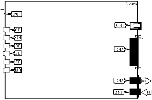
CONNECTIONS | ||||||
|
Function |
Label |
Function |
Label | |||
|
Power switch |
SW1 |
Phone line out |
CN3 | |||
|
DC power |
CN1 |
Phone line in |
CN4 | |||
|
RS-232/422 |
CN2 | |||||
|
DIAGNOSTIC LED(S) | |||
|
LED |
Color |
Status |
Condition |
|
CD |
Red |
On |
Carrier signal detected |
|
CD |
Red |
Off |
Carrier signal not detected |
|
OH |
Red |
On |
Modem is off-hook |
|
OH |
Red |
Off |
Modem is on-hook |
|
RD |
Red |
On |
Modem is receiving data |
|
RD |
Red |
Off |
Modem is not receiving data |
|
SD |
Red |
On |
Modem is transmitting data |
|
SD |
Red |
Off |
Modem is not transmitting data |
|
TR |
Red |
On |
DTR signal is high |
|
TR |
Red |
Off |
DTR signal is low |
|
MR |
Red |
On |
Power is on |
|
MR |
Red |
Off |
Power is off |
Proprietary AT Command Set
|
AUTO-RETRAIN - AUTO-FALLBACK/FALL-FORWARD | |
|
Type: |
Configuration |
|
Format: |
AT [cmds] %En [cmds] |
|
Description: |
Controls auto-retrain mode and fallback/fall-forward |
|
Command |
Function |
|
í %E0 |
Auto-retrain disabled |
|
%E1 |
Auto-retrain enabled |
|
%E2 |
Auto-fallback/fall-forward enabled |
|
BIT-MAPPED REGISTER S14 | ||
|
Format: |
AT [cmds] S14=n [cmds] | |
|
Default: |
138 | |
|
Range: |
0-174 | |
|
Unit: |
Bit-mapped | |
|
Description: |
Controls echo, result codes and display, dial mode, and answer/originate mode. | |
|
Bit |
Value |
Function |
|
0 |
í 0 |
Not used |
|
1 |
0 í 1 |
Command echo disabled Command echo enabled |
|
2 |
í 01 |
Result codes enabled Result codes disabled |
|
3 |
0 í 1 |
Display result codes in numeric format Display result codes in verbose format |
|
4 |
í 0 |
Not used |
|
5 |
í 01 |
Tone dial enabled Pulse dial enabled |
|
6 |
í 0 |
Not used |
|
7 |
0 í 1 |
Answer mode enabled Originate mode enabled |
|
BIT-MAPPED REGISTER S21 | ||
|
Format |
AT [cmds] S21=n [cmds] | |
|
Default: |
52 | |
|
Range: |
0-253 | |
|
Unit: |
Bit-mapped | |
|
Description: |
Selects jack type, CTS/DCD/DSR signals, low DTR action, and the long space disconnect function. | |
|
Bit |
Value |
Function |
|
0 |
í 01 |
Selects RJ-11, RJ-41S, or RJ45S jack Selects RJ-12 or RJ-13 jack |
|
1 |
í 0 |
Not used |
|
2 |
0 í 1 |
CTS forced high CTS follows RTS |
|
4, 3 |
00 01 í 1011 |
DTR signal ignored Modem goes to command mode on low DTR Modem disconnects on low DTR; Auto-Answer is disabled. Modem is initialized on low DTR |
|
5 |
0 í 1 |
DCD forced high DCD normal |
|
6 |
í 01 |
DSR forced high DSR normal |
|
7 |
í 01 |
Long space disconnect function disabled Long space disconnect function enabled |
|
BIT-MAPPED REGISTER S22 | ||
|
Format |
AT [cmds] S22=n [cmds] | |
|
Default: |
117 | |
|
Range: |
0-127 | |
|
Unit: |
Bit-mapped | |
|
Description: |
Controls speaker volume and controls, and limits results codes. | |
|
Bit |
Value |
Function |
|
1, 0 |
00 í 0110 11 |
Volume off Low level volume Medium level volume High level volume |
|
3, 2 |
00 í 0110 11 |
Speaker off Speaker off on carrier Speaker always on Speaker on during handshake |
|
6 - 4 |
000 100 101 110 í 111 |
Basic result codes only enabled Basic and connection speed result codes enabled Basic and connection speed result codes and dialtone detection enabled All result codes except dialtone detection enabled All result codes enabled |
|
BIT-MAPPED REGISTER S23 | ||
|
Format |
AT [cmds] S23=n [cmds] | |
|
Default: |
61 | |
|
Range: |
0-189 | |
|
Unit: |
Bit-mapped | |
|
Description: |
Grants/denies remote digital loopback, controls DTE rate and parity, and sets guard tone. | |
|
Bit |
Value |
Function |
|
0 |
0 í 1 |
Remote digital loopback denied Remote digital loopback allowed |
|
3 - 1 |
000 001 010 011 100 101 í 110 |
Sets serial port speed to 0-300bps Sets serial port speed to 600bps Sets serial port speed to 1200bps Sets serial port speed to 2400bps Sets serial port speed to 4800bps Sets serial port speed to 9600bps Sets serial port speed to 19200bps |
|
5, 4 |
00 01 10 í 11 |
Parity even Not used Parity odd No Parity |
|
6 |
í 0 |
Not used |
|
7 |
í 01 |
Guard tone disabled Guard tone disabled |
|
BIT-MAPPED REGISTER S27 | ||
|
Format |
AT [cmds] S27=n [cmds] | |
|
Default: |
73 | |
|
Range: |
0-111 | |
|
Unit: |
Bit-mapped | |
|
Description: |
Selects synchronous/asynchronous mode, line type, clock source, and ITU-T/Bell modes. | |
|
Bit |
Value |
Function |
|
3, 1, 0 |
000 001 010 011 100 í 101111 |
Asynchronous mode, serial port speed follows connect speed Asynchronous off-line command mode and synchronous connect mode Asynchronous off-line command mode; modem auto-dials first number in directory, then synchronous connect mode Asynchronous off-line command mode on low DTR, synchronous connect mode on high DTR Not used Error correction mode Buffered asynchronous mode |
|
2 |
í 01 |
Switched line Leased line |
|
5, 4 |
í 0001 10 |
Local modem generates transmit clock source Local DTE generates transmit clock source Remote DCE/DTE generates transmit clock source |
|
6 |
í 01 |
ITU/T mode Bell mode |
|
BIT-MAPPED REGISTER S28 | ||
|
Format |
AT [cmds] S28=n [cmds] | |
|
Default: |
0 | |
|
Range: |
0-24 | |
|
Unit: |
Bit-mapped | |
|
Description: |
Controls pulse dialing. | |
|
Note: |
AT&P returns ‘OK’ if valid, S28=0 should be set at all times. | |
|
Bit |
Value |
Function |
|
2 - 0 |
í 000 |
Not used |
|
4, 3 |
í 0001 10 11 |
39ms make/61ms break at 10pps 33ms make/67ms break at 10pps 39ms make/61ms break at 20pps 33ms make/67ms break at 20pps |
|
BIT-MAPPED REGISTER S31 | |||
|
Format: |
AT [cmds] S31=n [cmds] | ||
|
Default: |
194 | ||
|
Range: |
0-10 | ||
|
Description: |
Select automode and extended result code format. | ||
|
Bit |
Value |
Function | |
|
0 |
í 0 |
Not used | |
|
1 |
0 í 1 |
Auto-mode detection disabled In originate mode, handshake begins at line speed designated by the S37 register. Modem can shift to a slower speed if necessary. In answer mode, handshake attempted with the following protocols in order - V.FC, V.32bis, V.32, V.22bis, V.22 or Bell 212, V.21, and Bell 103 | |
|
3, 2 |
í 0001 10 |
Enables CONNECT result codes to report DTE speed Full reporting of CONNECT result codes Enables CONNECT result codes to report DCE speed | |
|
7 - 4 |
í 1100 |
Not used | |
|
BIT-MAPPED REGISTER S40 | ||
|
Format |
AT [cmds] S40=n [cmds] | |
|
Default: |
105 | |
|
Range: |
0-233 | |
|
Unit: |
Bit-mapped | |
|
Description: |
Controls break handling, and block size. | |
|
Bit |
Value |
Function |
|
2 - 0 |
í 001 |
Not used |
|
5, 4, 3 |
000 001 010 011 100 í 101 |
\K0 \K1 \K2 \K3 \K4 \K5 |
|
7, 6 |
00 í 0110 11 |
MNP block size is 64 characters MNP block size is 128 characters MNP block size is 192 characters MNP block size is 256 characters |
|
BIT-MAPPED REGISTER S41 | ||
|
Format |
AT [cmds] S41=n [cmds] | |
|
Default: |
3 | |
|
Range: |
0-91 | |
|
Unit: |
Bit-mapped | |
|
Description: |
Selects compression, auto-retrain and auto-fallback/fall-forward, flow control, and MNP mode. | |
|
Bit |
Value |
Function |
|
1 - 0 |
00 01 10 í 11 |
Data compression disabled MNP5 enabled V.42bis enabled MNP5 and V.42bis enabled |
|
6, 2 |
í 0001 10 |
Auto-retrain disabled Auto-retrain enabled Auto-fallback/fall-forward enabled |
|
3 |
í 01 |
Flow control disabled Flow control enabled |
|
4 |
í 01 |
Stream mode for MNP Block mode for MNP |
|
BREAK SEND | |
|
Type: |
Configuration |
|
Format: |
AT [cmds] \Bn [cmds] |
|
Default: |
3 |
|
Range: |
1-9 |
|
Unit: |
.1 second |
|
Description: |
Sends break to modem |
|
BREAK TYPE | ||||
|
Type: |
Configuration | |||
|
Format: |
AT [cmds] \Kn [cmds] | |||
|
Description: |
Configures action of break signal | |||
|
Command |
Break from DTE |
Modem receives \B |
Break received from remote modem | |
|
\K0 |
Online command mode enabled, send no break to remote modem |
Break sent to remote modem and buffers cleared |
Buffers cleared, break sent to DTE | |
|
\K1 |
Break sent to remote modem and buffers cleared |
Break sent to remote modem and buffers cleared |
Buffers cleared, break sent to DTE | |
|
\K2 |
Online command mode enabled, send no break to remote modem |
Send break to remote modem immediately |
Break sent immediately to DTE | |
|
\K3 |
Send break to remote modem immediately |
Send break to remote modem immediately |
Break sent immediately to DTE | |
|
\K4 |
Online command mode enabled, send no break to remote modem |
Send break with transmitted data |
Break sent with received data to the DTE | |
|
í \K5 |
Send break with transmitted data |
Send break with transmitted data |
Break sent with received data to the DTE | |
|
COMPRESSION | |
|
Type: |
Configuration |
|
Format: |
AT [cmds] %Cn [cmds] |
|
Description: |
Selects data compression |
|
Command |
Function |
|
%C0 |
Data compression disabled |
|
%C1 |
MNP5 enabled |
|
%C2 |
V.42bis enabled |
|
í %C3 |
MNP5 and V.42bis enabled |
|
CONNECT MODE | |
|
Type: |
Configuration |
|
Format: |
AT [cmds] \Nn [cmds] |
|
Description: |
Controls the type of connection the modem will operate in |
|
Command |
Function |
|
\N0 |
Normal mode enabled |
|
\N1 |
Direct mode enabled |
|
\N2 |
Reliable mode enabled |
|
\N3 |
Auto-reliable mode enabled |
|
\N4 |
V.42 reliable mode enabled |
|
\N5 |
MNP reliable mode enabled |
|
DIAL | |
|
Type: |
Immediate |
|
Format: |
AT [cmds] D<#> [cmds] |
|
Description: |
Dials telephone number according to any modifiers included in the string |
|
Note: |
Any combination of modifiers can be used to produce the desired dial functions in sequence. |
|
Modifier |
Function |
|
J |
Link will be negotiated at highest possible speed |
|
L |
Re-dial last number |
|
P |
Pulse dialing enabled |
|
R |
Accepted but not acted upon |
|
S=n |
Dial stored telephone number n |
|
T |
Tone dialing enabled |
|
W |
Dialing resumed following dial tone detection |
|
! |
Modem commanded to go off-hook for specified time before returning on-hook. |
|
@ |
Wait for quiet answer |
|
, |
Dialing paused for amount of time specified in S8 register |
|
; |
Modem returned to command state after dialing |
|
^ |
Enable calling tone |
|
FLASH DIAL MODIFIER TIME | |
|
Type: |
Register |
|
Format |
AT [cmds] S29=n [cmds] |
|
Default: |
0 |
|
Range: |
0-255 |
|
Unit: |
.01 second |
|
Description: |
Time the modem will go on-hook upon receiving the ! dial modifier in dial string. |
|
FLOW CONTROL | |
|
Type: |
Configuration |
|
Format: |
AT [cmds] \Gn [cmds] |
|
Description: |
Selects modem port flow control |
|
Command |
Function |
|
í \G0 |
Flow control disabled |
|
\G1 |
Flow control enabled |
|
FLOW CONTROL | |
|
Type: |
Read-only Register |
|
Format |
AT [cmds] S39? [cmds] |
|
Description: |
Displays the current flow control |
|
Value |
Meaning |
|
0 |
Flow control disabled |
|
í 3 |
RTS/CTS flow control enabled |
|
4 |
XON/XOFF flow control enabled |
|
5 |
Transparent XON/XOFF flow control enabled |
|
6 |
Both RTS/CTS and XON/XOFF flow control enabled |
|
FLOW CONTROL CHARACTER - XOFF | |
|
Type: |
Register |
|
Format: |
AT [cmds] S33=n [cmds] |
|
Default: |
19 |
|
Range: |
0-255 |
|
Unit: |
ASCII |
|
Description: |
Sets the character used to represent XOFF |
|
FLOW CONTROL CHARACTER - XON | |
|
Type: |
Register |
|
Format: |
AT [cmds] S32=n [cmds] |
|
Default: |
17 |
|
Range: |
0-255 |
|
Unit: |
ASCII |
|
Description: |
Sets the character used to represent XON |
|
INACTIVITY TIMER | |
|
Type: |
Register |
|
Format |
AT [cmds] S30=n [cmds] |
|
Default: |
0 |
|
Range: |
0-255 |
|
Unit: |
10 seconds |
|
Description: |
Maximum duration of DTE and DCE inactivity allowed prior to initiating hang-up process. S30=0 will disable timer. |
|
LINE SIGNAL LEVEL | |
|
Type: |
Immediate |
|
Format: |
AT [cmds] %L [cmds] |
|
Description: |
Returns a value which indicates the received line signal level (-dBm) |
|
LINE SIGNAL QUALITY | |
|
Type: |
Immediate |
|
Format: |
AT [cmds] %Q [cmds] |
|
Description: |
Returns a value which indicates line signal quality |
|
MAXIMUM BLOCK SIZE FOR TRANSMISSION | |
|
Type: |
Configuration |
|
Format: |
AT [cmds] \An [cmds] |
|
Description: |
Sets the maximum transmittable block size |
|
Command |
Function |
|
\A0 |
MNP block size is 64 characters |
|
í \A1 |
MNP block size is 128 characters |
|
\A2 |
MNP block size is 192 characters |
|
\A3 |
MNP block size is 256 characters |
|
MNP - STREAM/BLOCK MODE | |
|
Type: |
Configuration |
|
Format: |
AT [cmds] \Ln [cmds] |
|
Description: |
Selects the transfer mode for MNP link |
|
Command |
Function |
|
í \L0 |
Stream mode for MNP enabled |
|
\L1 |
Block mode for MNP enabled |
|
REPORT INFORMATION | |
|
Type: |
Immediate |
|
Format: |
AT [cmds] In [cmds] |
|
Description: |
Displays information requested |
|
Command |
Function |
|
I0 |
Reports product code |
|
I1 |
Reports ROM checksum |
|
I2 |
Tests and compares ROM checksum, reports ‘OK’. |
|
I3 |
Reports modem model and firmware revision |
|
I4 |
Reports modem identifier string |
|
I5 |
Reports country code |
|
I6 |
Reports modem series identifier string |
|
TEST MODES | ||
|
Type: |
Register | |
|
Format: |
AT [cmds] S16=n [cmds] | |
|
Default: |
0 | |
|
Range: |
0-125 | |
|
Unit: |
Bit-mapped | |
|
Description: |
Controls loopback tests: analog, digital, remote digital, and self tests. | |
|
Bit |
Value |
Function |
|
0 |
í 01 |
Local analog loopback not in progress Local analog loopback in progress |
|
1 |
í 0 |
Not used |
|
2 |
í 01 |
Local digital loopback not in progress Local digital loopback in progress |
|
3 |
í 01 |
Modem not in remote digital loopback Remote digital loopback in progress |
|
4 |
í 01 |
Remote digital loopback not requested Remote digital loopback requested |
|
5 |
í 01 |
Remote digital loopback w/ self-test not in progress Remote digital loopback w/ self-test in progress |
|
6 |
í 01 |
Local analog loopback w/ self-test not in progress Local analog loopback w/ self-test in progress |