PROMETHEUS PRODUCTS, INC.
CYBERPORT PRO PC288IV, CYBERPHONE PC288IVSP
|
Card Type |
Fax, Modem (asynchronous/synchronous) |
|
Chip Set |
Unidentified |
|
I/O Options |
Speakerphone, Voice-mail |
|
Maximum Data Rate |
28.8Kbps |
|
Maximum Fax Rate |
14.4Kbps |
|
Data Bus |
16-bit ISA |
|
Fax Class |
Class II |
|
Data Modulation Protocol |
Bell 103/212A ITU-T V.21, V.22, V.22bis, V.23, V.32, V.32bis, V.34 |
|
Fax Modulation Protocol |
ITU-T V.17, V.21CH2, V.27ter, V.29, V.33 |
|
Error Correction/Compression |
MNP5, V.42, V.42bis |
|
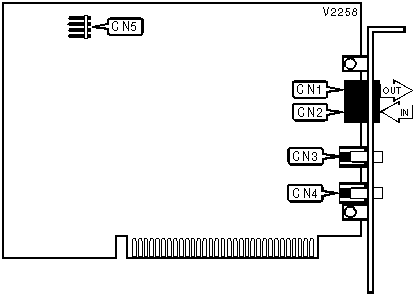
CONNECTIONS | ||||||
|
Function |
Label |
Function |
Label | |||
|
Line out |
CN1 |
Microphone |
CN4 | |||
|
Line in |
CN2 |
Sound card connector |
CN5 | |||
|
Speaker |
CN3 | |||||
Proprietary AT Command Set
|
ASYNCHRONOUS PROTOCOL (CONNCET MODE) | |
|
Type: |
Configuration |
|
Format: |
AT [cmds] \Nn [cmds] |
|
Description: |
Selects asynchronous protocol (connect mode) |
|
Command |
Function |
|
\N0 |
Normal mode enabled |
|
\N1 |
Direct mode enabled (V.14 asynchronous) |
|
\N2 |
MNP reliable mode enabled |
|
\N3 |
Auto-reliable mode enabled |
|
\N4 |
V.42 reliable mode enabled |
|
\N5 |
V.42 auto-reliable mode enabled |
|
\N6 |
Reliable mode enabled (V.13/simulated carrier control) |
|
AUTO-FALLBACK/FALL-FORWARD | |
|
Type: |
Configuration |
|
Format: |
AT [cmds] &An [cmds] |
|
Description: |
Controls auto-fallback/fall-forward |
|
Command |
Function |
|
&A0 |
Auto-fallback/fall-forward disabled |
|
&A1 |
Auto-fallback/fall-forward enabled |
|
AUTO-RELIABLE FALLBACK CHARACTER | |
|
Type: |
Configuration |
|
Format: |
AT [cmds] %An [cmds] |
|
Default: |
Unidentified |
|
Range: |
0-127 |
|
Unit: |
ASCII |
|
Description: |
Sets the character used as the auto-reliable fallback character |
|
Note: |
AT%A0 will disable this function. |
|
AUTO-RELIABLE TIME BUFFER CONFIGURATION | |
|
Type: |
Configuration |
|
Format: |
AT [cmds] \Cn [cmds] |
|
Description: |
Controls the handling of incoming data during auto-reliable time period |
|
Command |
Function |
|
\C0 |
Time-out and fallback, speed buffer, no data buffer |
|
\C1 |
Time-out and fallback, speed buffer, buffer receive data |
|
\C2 |
Auto-reliable, fallback with fallback character speed buffer, no receive data buffer |
|
\C3 |
Time-out and fallback, V.14, buffer receive data |
|
\C4 |
Time-out or fallback with fallback character, V.14, no data buffer |
|
BREAK HANDLING | ||
|
Type: |
Configuration | |
|
Format: |
AT [cmds] \Kn [cmds] | |
|
Description: |
Controls action of break character | |
|
Command |
Function | |
|
\K0 |
Send break to remote modem immediately and buffered cleared | |
|
\K1 |
Send break to remote modem immediately and buffers saved | |
|
\K2 |
Timed break and buffers saved | |
|
\K3 |
Break ignored | |
|
\K4 |
Timed break until no break character and buffers saved | |
|
\K5 |
Timed break until no break character and buffers saved | |
|
BUSY-OUT | ||
|
Type: |
Configuration | |
|
Format: |
AT [cmds] %Bn [cmds] | |
|
Description: |
Controls busy-out options | |
|
Command |
Function | |
|
%B0 |
Disable busy-out | |
|
%B1 |
Enable busy-out on loss of DTR | |
|
%B2 |
Enable busy-out in local analog loopback test | |
|
%B3 |
Enable busy-out in local analog loopback test, or on loss of RTS or DTR | |
|
%B4 |
Enable busy-out on loss of RTS | |
|
CALL PROGRESS MONITOR | ||
|
Type: |
Configuration | |
|
Format: |
AT [cmds] %Rn [cmds] | |
|
Description: |
Sets the call progress monitor message speed | |
|
Command |
Function | |
|
%R0 |
Autobaud | |
|
%R1 |
Send at last connect speed | |
|
%R2 |
Send at 300bps | |
|
%R3 |
Send at 1200bps | |
|
%R4 |
Send at 2400bps | |
|
%R5 |
Send at 4800bps | |
|
%R6 |
Send at 7200bps | |
|
%R7 |
Send at 9600bps | |
|
%R8 |
Send at 12Kbps | |
|
%R9 |
Send at 14.4Kbps | |
|
%R10 |
Send at 16.8Kbps | |
|
%R11 |
Send at 19.2Kbps | |
|
%R12 |
Send at 21.6Kbps | |
|
%R13 |
Send at 24Kbps | |
|
%R14 |
Send at 26.4Kbps | |
|
%R15 |
Send at 28.8Kbps | |
|
%R16 |
Send at 38.4Kbps | |
|
%R17 |
Send at 57.6Kbps | |
|
%R18 |
Send at 76.8Kbps | |
|
%R19 |
Send at 115.2Kbps | |
|
%R20 |
Send at 128Kbps | |
|
CHARACTER ABORT | |
|
Type: |
Configuration |
|
Format: |
AT [cmds] %Kn [cmds] |
|
Description: |
Controls character abort |
|
Command |
Function |
|
%K0 |
Character abort enabled (2 second delay) |
|
%K1 |
Character abort disabled |
|
CHARACTER LENGTH | ||
|
Type: |
Configuration | |
|
Format: |
AT [cmds] \Bn [cmds] | |
|
Description: |
Controls character length: data bits, parity, stop bits. | |
|
Command |
Function | |
|
\B0 |
6 data bits, no parity, 1 stop bit | |
|
\B1 |
7 data bits, no parity, 1 stop bit | |
|
\B2 |
7 data bits, \P sets parity, 1 stop bit | |
|
\B3 |
8 data bits, no parity, 1 stop bit | |
|
\B4 |
7 data bits, \P sets parity, 2 stop bits | |
|
\B5 |
8 data bits, \P sets parity, 1 stop bit | |
|
COMPRESSION | |
|
Type: |
Configuration |
|
Format: |
AT [cmds] %Cn [cmds] |
|
Description: |
Selects data compression |
|
Command |
Function |
|
%C0 |
Data compression disabled |
|
%C1 |
Enabled in both transmit and receive paths |
|
%C2 |
Enabled in transmit path only in V.42bis |
|
%C3 |
Enabled in receive path only in V.42bis |
|
COMMUNICATIONS MODE | |
|
Type: |
Configuration |
|
Format: |
AT [cmds] &Mn [cmds] |
|
Description: |
Selects communications mode |
|
Command |
Mode |
|
&M0 |
Asynchronous mode |
|
&M1 |
Synchronous mode with DTR to data delay (S25 register) |
|
CONNECT MESSAGE TYPE | |
|
Type: |
Configuration |
|
Format: |
AT [cmds] \Vn [cmds] |
|
Description: |
Selects connect message |
|
Command |
Function |
|
\V0 |
Extended result codes disabled, standard connect message displayed |
|
í \V1 |
Extended result codes enabled, MNP class and DTE speed displayed |
|
\V2 |
Extended result codes enabled, /REL and DCE speed displayed |
|
\V3 |
Extended result codes enabled, connection speed is DTE speed |
|
DATA CARRIER DETECT (DCD) | |
|
Type: |
Configuration |
|
Format: |
AT [cmds] &Cn [cmds] |
|
Description: |
Controls DCD signal |
|
Command |
Function |
|
&C0 |
DCD forced high |
|
&C1 |
DCD forced high after CD signal detected |
|
&C2 |
DCD forced high, toggle DCD on disconnect |
|
DATA SET READY (DSR) | |
|
Type: |
Configuration |
|
Format: |
AT [cmds] &Sn [cmds] |
|
Description: |
Selects DSR options |
|
Command |
Function |
|
&S0 |
DSR forced high, toggle DSR on disconnect |
|
&S1 |
DSR high only while modem is handshaking or connected |
|
&S2 |
DSR high only while modem is connected |
|
&S3 |
DSR forced high |
|
DATA TERMINAL READY (DTR) | ||
|
Type: |
Configuration | |
|
Format: |
AT [cmds] &Dn [cmds] | |
|
Description: |
Selects modem response to DTR | |
|
Command |
Function | |
|
&D0 |
Modem does not respond to DTR, DTR forced high | |
|
&D1 |
Modem goes to command mode after DTR goes is off | |
|
&D2 |
Modem goes on-hook after DTR goes off | |
|
&D3 |
Modem is initialized after DTR goes off | |
|
DIAL | |
|
Type: |
Immediate |
|
Format: |
AT [cmds] D<#> [cmds] |
|
Description: |
Dials telephone number according to any modifiers included in the string |
|
Note: |
Any combination of modifiers can be used to produce the desired dial functions in sequence. |
|
Modifier |
Function |
|
Ln |
Link to cell n if modem cannot connect |
|
P |
Pulse dialing enabled |
|
R |
Answer mode enabled, originate mode disabled following handshake initiation |
|
Sn |
Dial stored telephone number n |
|
T |
Tone dialing enabled |
|
W |
Dialing resumed following dial tone detection after amount of time specified in S6 register |
|
! or & |
Modem commanded to go off-hook for .5 second before returning on-hook |
|
, or < |
Dialing paused for amount of time specified in S8 register |
|
:n |
Re-dial n times until connected |
|
; |
Modem returned to command state after dialing |
|
@ |
Wait for quiet answer for amount of time specified in S7 register |
|
DIAL-UP HANDSHAKE | ||
|
Type: |
Configuration | |
|
Format: |
AT [cmds] &Hn [cmds] | |
|
Description: |
Select the handshake mode | |
|
Command |
Function | |
|
&H0 |
Set to GDC fast auto (28.8K - 300bps) | |
|
&H1 |
Set to GDC fast only (28.8K - 9600bps) | |
|
&H2 |
Set to V.32bis auto (14.4K - 300bps) | |
|
&H3 |
Set to V.32bis only (14.4K - 4800bps) | |
|
&H4 |
Set to V.32 auto (9600 - 300bps) | |
|
&H5 |
Set to V.32 only (9600 - 4800bps) | |
|
&H6 |
Set to V.22bis only (2400 - 1200bps) | |
|
&H7 |
Set to V.22 only (1200bps) | |
|
&H8 |
Set to Bell 212A only (1200bps) | |
|
&H9 |
Set to Bell 103 only (300bps) | |
|
&H10 |
Set to V.21 only (300bps) | |
|
DISPLAY STORED NUMBERS | |
|
Type: |
Immediate |
|
Format: |
AT [cmds] &V [cmds] |
|
Description: |
Displays all stored phone numbers in sequence (0-3) |
|
DSR | ||
|
Type: |
Configuration | |
|
Format: |
AT [cmds] %Sn [cmds] | |
|
Description: |
Controls DSR signal | |
|
Command |
Function | |
|
&S0 |
DSR forced high, DSR forced low on disconnect | |
|
&S1 |
DSR normal | |
|
&S2 |
DSR follows CD | |
|
&S3 |
DSR forced high | |
|
DSR - TEST MODE | ||
|
Type: |
Configuration | |
|
Format: |
AT [cmds] %Dn [cmds] | |
|
Description: |
Controls DSR signal during test modes | |
|
Command |
Function | |
|
%D0 |
DSR forced high during local analog loopback test | |
|
%D1 |
DSR forced low during this test | |
|
DTE INTERFACE CONTROLLED TESTS | ||
|
Type: |
Configuration | |
|
Format: |
AT [cmds] %En [cmds] | |
|
Description: |
Controls test modes using DTE interface pins | |
|
Command |
Function | |
|
%E0 |
Disable tests using DTE interface pins | |
|
%E1 |
Enable tests using DTE interface pins (V.24 circuit 140 and 141) | |
|
DTE SPEED | ||
|
Type: |
Configuration | |
|
Format: |
AT [cmds] \Tn [cmds] | |
|
Description: |
Sets DTE speed | |
|
Command |
Function | |
|
\T0 |
Autobaud, AT%R sets call progress monitor message speed | |
|
\T1 |
Set to last AT speed | |
|
\T2 |
Set to 300bps | |
|
\T3 |
Set to 1200bps | |
|
\T4 |
Set to 2400bps | |
|
\T5 |
Set to 4800bps | |
|
\T6 |
Set to 7200bps | |
|
\T7 |
Set to 9600bps | |
|
\T8 |
Set to 12Kbps | |
|
\T9 |
Set to 14.4Kbps | |
|
\T10 |
Set to 16.8Kbps | |
|
\T11 |
Set to 19.2Kbps | |
|
\T12 |
Set to 21.6Kbps | |
|
\T13 |
Set to 24Kbps | |
|
\T14 |
Set to 26.4Kbps | |
|
\T15 |
Set to 28.8Kbps | |
|
\T16 |
Set to 38.4Kbps | |
|
\T17 |
Set to 57.6Kbps | |
|
\T18 |
Set to 76.8Kbps | |
|
\T19 |
Set to 115.2Kbps | |
|
\T20 |
Set to 128Kbps | |
|
DTR DIALING | ||
|
Type: |
Configuration | |
|
Format: |
AT [cmds] %Zn [cmds] | |
|
Description: |
Controls DTR dialing | |
|
Command |
Function | |
|
%Z0 |
Ignore | |
|
%Z1=n |
Dial cell n | |
|
%Z2 |
Go off-hook, try to handshake | |
|
FACTORY DEFAULT PROFILE | ||
|
Type: |
Configuration | |
|
Format: |
AT [cmds] &Fn [cmds] | |
|
Description: |
Sets values in active profile to values found in the default profile | |
|
Command |
Function | |
|
&F0 |
Dial-up, asynchronous, V.42, and V.42bis modes enabled | |
|
&F1 |
Dial-up, synchronous modes enabled | |
|
FLOW CONTROL | |
|
Type: |
Configuration |
|
Format: |
AT [cmds] \Gn [cmds] |
|
Description: |
Selects modem port flow control |
|
Command |
Function |
|
\G0 |
Flow control disabled |
|
\G1 |
Enable XON/XOFF in both transmit and receive paths |
|
\G2 |
Enable in transmit path only |
|
\G3 |
Enable in both transmit and receive paths, with pass-through |
|
FLOW CONTROL TYPE | |
|
Type: |
Configuration |
|
Format: |
AT [cmds] \Qn [cmds] |
|
Description: |
Sets type of flow control used by modem |
|
Command |
Function |
|
\Q0 |
Flow control disabled |
|
\Q1 |
Bi-directional XON/XOFF flow control enabled |
|
\Q2 |
CTS flow control enabled |
|
\Q3 |
RTS/CTS flow control enabled |
|
\Q4 |
Unidirectional XON/XOFF flow control by DCE enabled |
|
LINE SIGNAL QUALITY | ||
|
Type: |
Configuration | |
|
Format: |
AT [cmds] %Q [cmds] | |
|
Description: |
Controls how the modem responds to poor signal quality | |
|
Command |
Function | |
|
%Q0 |
No retraining, disabled | |
|
%Q1 |
Retrain up to 3 times, disconnect if quality is still not good | |
|
%Q2 |
Retrain until signal quality is good | |
|
OVERSPEED CORRECTION | |
|
Type: |
Configuration |
|
Format: |
AT [cmds] \An [cmds] |
|
Description: |
Controls overspeed correction |
|
Command |
Function |
|
\A0 |
Connect with 1.25% (nominal) asynchronous overspeed correction |
|
\A1 |
Connect with 2.5% (extended) overspeed correction |
|
PARITY | ||
|
Type: |
Configuration | |
|
Format: |
AT [cmds] \Pn [cmds] | |
|
Description: |
Selects the type of parity used | |
|
Command |
Function | |
|
\P0 |
Even parity | |
|
\P1 |
Space parity | |
|
\P2 |
Odd parity | |
|
\P3 |
Mark parity | |
|
\P4 |
Automatic (from last AT command) | |
|
REPORT INFORMATION | |
|
Type: |
Immediate |
|
Format: |
AT [cmds] In [cmds] |
|
Description: |
Displays information requested |
|
Command |
Function |
|
I0 |
Reports product code |
|
I1 |
Reports ROM checksum |
|
I2 |
Tests and reports ROM checksum |
|
I3 |
Reports firmware revision level |
|
I4 |
Reports a summary of all S-registers |
|
RETRANSMISSION COUNTER | |
|
Type: |
Register |
|
Format: |
AT [cmds] S70=n [cmds] |
|
Default: |
100 |
|
Range: |
0-255 |
|
Unit: |
Unidentified |
|
Description: |
Controls how many retransmission’s are accounted for |
|
SYNCHRONOUS PROTOCOL (CONNECT MODE) | |
|
Type: |
Configuration |
|
Format: |
AT [cmds] \Mn [cmds] |
|
Description: |
Selects synchronous protocol |
|
Command |
Function |
|
\M0 |
Normal synchronous mode enabled |
|
\M1 |
V.13 synchronous mode enabled (simulated controlled carrier) |
|
TEST MODES | |
|
Type: |
Immediate |
|
Format: |
AT [cmds] &Tn |
|
Description: |
Selects test options |
|
Command |
Function |
|
&T0 |
End current test |
|
&T1 |
Begin local analog loopback test |
|
&T3 |
Begin local digital loopback test |
|
&T4 |
Enable remote digital loopback test |
|
&T5 |
Disable remote digital loopback test |
|
&T6 |
Disable remote digital loopback test |
|
&T7 |
Enable remote digital loopback with self-test |
|
&T8 |
Enable local analog loopback and self-test |
|
&T9 |
Enable End-to-End self-test |
|
TRELLIS CODING | ||
|
Type: |
Configuration | |
|
Format: |
AT [cmds] &Un [cmds] | |
|
Description: |
Controls trellis coding | |
|
Command |
Function | |
|
&U0 |
Enabled trellis coding | |
|
&U1 |
Disabled trellis coding | |
|
V.13 - SIMULATED CONTROLLED CARRIER | ||
|
Type: |
Configuration | |
|
Format: |
AT [cmds] &En [cmds] | |
|
Description: |
Controls V.13 carrier in direction selected | |
|
Command |
Function | |
|
&E0 |
Enabled in both transmit and receive paths | |
|
&E1 |
Enabled in transmit path only | |
|
&E2 |
Enabled in receive path only | |