E-TECH RESEARCH, INC.
PC288MX (REV. 2)
|
Modem Type |
Data (synchronous/asynchronous)/Fax |
|
Maximum Data Rate |
28.8Kbps |
|
Maximum Fax Rate |
14.4Kbps |
|
Data Bus |
8-bit ISA |
|
Fax Class |
Class I |
|
Data Modulation Protocol |
Bell 103A/212A ITU-T V.21, V.22, V.22bis, V.23, V.32, V.32bis, V.34 AT&T V.32terbo |
|
Fax Modulation Protocol |
ITU-T V.17, V.21Ch2, V.27ter, V.29 |
|
Error Correction/Compression |
MNP5, V.42, V.42bis |
|
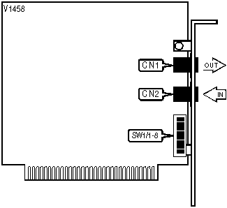
CONNECTIONS | |||
|
Purpose |
Location |
Purpose |
Location |
|
Line out |
CN1 |
Line in |
CN2 |
|
BASE I/O ADDRESS SELECTION | ||||
|
Port |
SW1/1 |
SW1/2 |
SW1/3 |
SW1/5 |
|
COM1: (3F8h) |
On |
Off |
On |
Off |
|
COM2: (2F8h) |
On |
Off |
Off |
On |
|
COM3: (3E8h) |
Off |
On |
On |
Off |
|
COM4: (2E8h) |
Off |
On |
Off |
On |
|
INTERRUPT SELECTION | ||||
|
IRQ |
SW1/4 |
SW1/6 |
SW1/7 |
SW1/8 |
|
2 |
Off |
Off |
Off |
On |
|
3 |
Off |
On |
Off |
Off |
|
4 |
On |
Off |
Off |
Off |
|
5 |
Off |
Off |
On |
Off |
Proprietary AT Command Set
|
AUTO FALLBACK CHARACTER | |
|
Type: |
Register |
|
Format: |
AT [cmds] S43=n [cmds] |
|
Example: |
AT S43=13 <CR> |
|
Description: |
Set auto fallback character during MNP negotiation. (%An) |
|
Notes |
S43=0, disabled. S43=(1 - 127), enabled. |
|
AUTO FALL FORWARD/FALLBACK | |
|
Type: |
Configuration |
|
Format: |
AT [cmds] %Gn [cmds] |
|
Example: |
AT %G &W <CR> |
|
Description: |
Selects auto fallback. |
|
Command |
Function |
|
%G0 |
Fallback disabled. |
| » %G1 |
Fallback enabled. |
|
AUTO-RELIABLE FALLBACK CHARACTER | |
|
Type: |
Configuration |
|
Format: |
AT [cmds] %An [cmds] |
|
Example: |
AT%A20 <CR> |
|
Default: |
13 |
|
Range: |
0-127 |
|
Unit: |
ASCII. |
|
Description: |
Sets the character used as the auto-reliable fallback character. %A0 will disable this function. |
|
AUTO-RELIABLE TIME BUFFER CONFIGURATION | |
|
Type: |
Configuration |
|
Format: |
AT [cmds] \Cn [cmds] |
|
Example: |
AT \C1 &W <CR> |
|
Description: |
Controls the handling of incoming data during auto-reliable time period. |
|
Command |
Function |
| » \CO |
Data is discarded. |
|
\C1 |
Data is buffered. |
|
\C2 |
Data is discarded, sets to normal mode and sends auto-reliable character to serial port. |
|
AUTO-RETRAIN | |
|
Type: |
Configuration |
|
Format: |
AT %En |
|
Example: |
AT %E1 <CR> |
|
Description: |
Selects auto-retrain mode. |
|
Command |
Function |
|
%E0 |
Auto-retrain disabled. |
| » %E1 |
Auto-retrain enabled. |
|
%E2 |
Do not hang up and auto-retrain disabled. |
|
AUTO SLEEP TIMER | |
|
Format |
AT [cmds] S46=n [cmds] |
|
Example: |
AT S46= 100 <CR> |
|
Default: |
255 |
|
Range: |
0 - 255 |
|
Unit: |
.1 second. |
|
Description: |
Maximum duration of DTE and DCE inactivity allowed prior to initiating low-power sleep mode. 255 = disable. |
|
BIT-MAPPED REGISTER S14 | |||
|
Format |
AT [cmds] S14? [cmds] | ||
|
Example: |
ATS14? <CR> | ||
|
Default: |
Read only | ||
|
Range: |
0-174 | ||
|
Unit: |
Bit-mapped. | ||
|
Description: |
Controls echo, result codes, result code display, dial mode, and answer/originate mode. | ||
|
Bit |
Value |
Meaning | |
|
0 |
0 |
Not used. | |
|
1 |
0 » 1 |
Command echo disabled. Command echo enabled. | |
|
2 |
» 0
1 |
Result codes enabled. Result codes disabled. | |
|
3 |
0 » 1 |
Display result codes in numeric format. Display result codes in verbose format. | |
|
4 |
0 |
Not used. | |
|
5 |
0 » 1 |
Tone dial enabled. Pulse dial enabled. | |
|
6 |
0 |
Not used. | |
|
7 |
0 » 1 |
Answer mode enabled. Originate mode enabled. | |
|
BIT-MAPPED REGISTER S21 | |||
|
Format |
AT [cmds] S21? [cmds] | ||
|
Example: |
ATS21? <CR> | ||
|
Default: |
Read only | ||
|
Range: |
0 - 124 | ||
|
Unit: |
Bit-mapped. | ||
|
Description: |
Controls CTS, low DTR action, and DCD signal. | ||
|
Bit |
Value |
Meaning | |
|
1, 0 |
00 |
Not used. | |
|
2 |
» 0
1 |
CTS follows RTS. Synchronous modes only. CTS forced high. | |
|
4, 3 |
00 01 » 10 11 |
DTR signal ignored. Modem goes to command mode on low DTR. Modem disconnects on low DTR. Auto-Answer is disabled. Modem is initialized on low DTR. | |
|
5 |
0 » 1 |
DCD forced high. DCD normal. | |
|
6 |
» 0
1 |
DSR forced high. DSR normal. | |
|
BIT-MAPPED REGISTER S22 | |||
|
Format |
AT [cmds] S22? [cmds] | ||
|
Example: |
ATS22? <CR> | ||
|
Default: |
Read only | ||
|
Range: |
0 - 255 | ||
|
Unit: |
Bit-mapped. | ||
|
Description: |
Controls volume and speaker settings, result codes, and make/break pulse ratio. | ||
|
Bit |
Value |
Meaning | |
|
1, 0 |
00 01 » 10 11 |
Lowest volume setting. Low volume setting. Medium volume setting Highest volume setting. | |
|
3, 2 |
00 » 01 10 11 |
Speaker disabled. Speaker enabled until carrier signal detected Speaker enabled. Speaker enabled following dialing, then disabled after carrier signal detected. | |
|
6, 5 ,4 |
000 100 101 110 » 111 |
Busy and dialtone detection disabled. Busy and dialtone detection disabled. Busy tone detection disabled, dialtone detection enabled. Busy tone detection enabled, dialtone detection disabled. Busy and dialtone detection enabled. | |
|
7 |
» 0
1 |
Pulse dialing at 39/61ms at 10pps. Pulse dialing at 33/67ms at 10pps. | |
|
BIT-MAPPED REGISTER S23 | |||
|
Format |
AT [cmds] S23? [cmds] | ||
|
Example: |
ATS23? <CR> | ||
|
Default: |
Read only | ||
|
Range: |
0-241 | ||
|
Unit: |
Bit-mapped. | ||
|
Description: |
Grants/denies remote digital loopback, controls parity, and sets guard tone. | ||
|
Bit |
Value |
Meaning | |
|
0 |
0 » 1 |
Remote digital loopback denied. Remote digital loopback allowed. | |
|
3, 2, 1 |
000 |
Not used. | |
|
5,4 |
00 » 01 10 11 |
Parity even. Parity Space. Parity odd. Parity Mark. | |
|
7, 6 |
» 00
01 10 |
Guard tone disabled. Guard tone 550Hz enabled. Guard tone 1800Hz enabled. | |
|
BIT-MAPPED REGISTER S27 | |||
|
Format |
AT [cmds] S27? [cmds] | ||
|
Example: |
AT S27? <CR> | ||
|
Default: |
Read only | ||
|
Range: |
0 - 127 | ||
|
Unit: |
Bit-mapped. | ||
|
Description: |
Selects sync/async mode, Line type, internal clock, and ITU-T/Bell modes. | ||
|
Bit |
Value |
Function | |
|
3, 1, 0 |
» 000
001 010 011 100 |
Asynchronous mode, serial port speed follows connect speed. Asynchronous command mode and synchronous connect mode. Asynchronous command mode and synchronous connect mode, DTR dialing enabled. Asynchronous command mode on low DTR, synchronous connect mode on high DTR. Hayes AutoSync™ mode - serial port locked at 9600bps. | |
|
2 |
» 0
1 |
Dial up line. Leased line. | |
|
5, 4 |
» 00
01 10 |
Internal DTE transmit clock source. External DTE transmit clock source. Slave DTE transmit clock source. | |
|
6 |
0 » 1 |
CCITT mode. Bell mode. | |
|
BIT-MAPPED REGISTER S44 | |||
|
Format |
AT [cmds] S44? [cmds] | ||
|
Example: |
AT S44? <CR> | ||
|
Default: |
Read only. | ||
|
Range: |
0-23 | ||
|
Unit: |
Bit-mapped. | ||
|
Description: |
Selects V.42 status, V.42bis, and fallback. | ||
|
Bit |
Value |
Meaning | |
|
0 |
0 » 1 |
V.42bis status disabled. V.42bis status enabled. | |
|
2, 1 |
00 01 10 » 11 |
V.42bis disabled. V.42bis when transmitting enabled. V.42bis when receiving enabled. V.42bis when transmitting/receiving enabled. | |
|
3 |
0 |
Not used. | |
|
4 |
0 » 1 |
Fallback disabled. Fallback enabled. | |
|
BIT-MAPPED REGISTER S51 | |||
|
Format |
AT [cmds] S51? [cmds] | ||
|
Example: |
AT S51? <CR> | ||
|
Default: |
Read only. | ||
|
Range: |
0 - 115 | ||
|
Unit: |
Bit-mapped. | ||
|
Description: |
Display flow control. | ||
|
Bit |
Value |
Meaning | |
|
2, 1, 0 |
000 001 010 » 011 |
Flow control disabled. XON/XOFF flow control enabled. CTS flow control to DTE enabled. RTS/CTS flow control enabled. | |
|
3 |
0 |
Not used. | |
|
4 |
» 0
1 |
Flow control disabled. Flow control to XON/XOFF flow enabled. | |
|
5 |
» 0
1 |
Serial speed locked. Serial speed follows connect speed. | |
|
7, 6 |
» 00
01 |
XON/XOFF signals trapped by local modem. XON/XOFF passed through local modem. | |
|
BIT-MAPPED REGISTER S54 | |||
|
Format |
AT [cmds] S54? [cmds] | ||
|
Example: |
AT S54? <CR> | ||
|
Default: |
Read only. | ||
|
Range: |
0 - 131 | ||
|
Unit: |
Bit-mapped | ||
|
Description: |
Displays the communication protocol for data calls, and protocol result code. | ||
|
Bit |
Value |
Meaning | |
|
0 |
0 1 |
B2 is enabled. B2 is not enabled. | |
|
1 |
0 1 |
B3 is enabled B3 is not enabled. | |
|
6 - 2 |
0 |
Not used. | |
|
7 |
0 1 |
Protocol result code disabled. Protocol result code enabled. | |
|
BREAK SEND | |
|
Type: |
Configuration |
|
Format: |
AT [cmds] \Bn [cmds] |
|
Example: |
AT \B3 &W <CR> |
|
Range: |
1-9 |
|
Unit: |
100 ms. |
|
Description: |
Sends break to modem. |
|
BREAK TYPE | ||||
|
Type: |
Configuration | |||
|
Format: |
AT [cmds] \Kn [cmds] | |||
|
Example: |
AT \K1 <CR> | |||
|
Description: |
Configures action of break signal. | |||
|
Command |
Break from DTE Reliable/Normal mode |
Break from DTE Direct mode |
Break from remote modem | |
|
\K0 |
Enter command mode, do not send break to remote modem. |
Send break to remote modem immediately, then enter command mode. |
Buffers cleared and break sent to DTE. | |
|
\K1 |
Buffers cleared and break sent to remote modem. |
Send break to remote modem immediately. |
Buffers cleared and break sent to DTE. | |
|
\K2 |
Enter command mode, do not send break to remote modem. |
Send break to remote modem immediately, then enter command mode. |
Send break to DTE immediately. | |
|
\K3 |
Send break to remote modem immediately. |
Send break to remote modem immediately. |
Send break to DTE immediately. | |
|
\K4 |
Enter command mode, do not send break to remote modem. |
Send break to remote modem immediately, then enter command mode. |
Break sent with received data to the DTE. | |
| » \K5 |
Send break with transmitted data. |
Send break to remote modem immediately. |
Break sent with received data to the DTE. | |
|
COMPRESSION | |
|
Type: |
Configuration |
|
Format: |
AT %Cn |
|
Example: |
AT *EC0 %C1 *AP0 <CR> |
|
Description: |
Selects data compression. |
|
Command |
Function |
|
%C0 |
Data compression disabled. |
|
%C1 |
MNP 5 enabled. |
|
%C2 |
V.42bis enabled. |
| » %C3 |
MNP 5 and V.42bis enabled. |
|
COMPRESSION | |
|
Type: |
Configuration |
|
Format: |
AT $Cn |
|
Example: |
AT *EC0 $C1 *AP0 <CR> |
|
Description: |
Selects data compression. |
|
Command |
Function |
|
$C0 |
Data compression disabled. |
| » $C1 |
Data compression enabled. |
|
CONNECT MODE | |
|
Type: |
Configuration |
|
Format: |
AT [cmds] \Nn [cmds] |
|
Example: |
AT \N1 DT555-1212 <CR> |
|
Description: |
Sets connect mode. |
|
Command |
Function |
|
\N0 |
Normal mode enabled. |
|
\N1 |
Direct mode enabled. |
|
\N2 |
MNP mode only enabled. |
| » \N3 |
LAP-M mode with fallback to MNP and normal modes enabled. |
|
\N4 |
LAP-M mode with fallback to MNP enabled. |
|
\N5 |
LAP-M mode only enabled. |
|
CONNECT MODE | |
|
Type: |
Configuration |
|
Format: |
AT [cmds] $En [cmds] |
|
Example: |
AT $E1 DT555-1212 <CR> |
|
Description: |
Sets connect mode. |
|
Command |
Function |
|
$E0 |
Normal mode enabled. |
|
$E1 |
MNP mode with fallback to normal mode enabled. |
|
$E2 |
MNP mode only enabled. |
| » $E3 |
LAP-M mode with fallback to MNP and normal modes enabled. |
|
$E4 |
LAP-M mode only enabled. |
|
DISPLAY AUTO-RELIABLE BUFFER | |
|
Type: |
Register |
|
Format: |
AT [cmds] S48? [cmds] |
|
Example: |
AT S48? <CR> |
|
Default: |
Read only. |
|
Description: |
Displays auto-reliable buffer settings. (\Cn) |
|
Value |
Meaning |
| » 0 |
Data is discarded. |
|
1 |
Data is buffered. |
|
2 |
Data is discarded, modem returns to normal mode on receiving auto-reliable fallback character. |
|
DISPLAY CONNECT MESSAGE | |
|
Type: |
Register |
|
Format |
AT [cmds] S41? [cmds] |
|
Example: |
AT S41? <CR> |
|
Default: |
Read only. |
|
Description: |
Connect message display. (Wn) |
|
Value |
Meaning |
| » 0 |
Connect with DTE speed. |
|
1 |
Connect with carrier, protocol, and compression. |
|
2 |
Connect with DCE speed. |
|
DISPLAY FAX/DATA MODE | |
|
Type: |
Register |
|
Format: |
AT [cmds] S50? [cmds] |
|
Example: |
AT S50? <CR> |
|
Default: |
Read only. |
|
Description: |
Displays data or FAX mode. |
|
Value |
Meaning |
| » 0 |
Data mode enabled. |
|
1 |
FAX mode enabled. |
|
DISPLAY FLOW CONTROL TYPE | |
|
Type: |
Register |
|
Format: |
AT [cmds] S52?[cmds] |
|
Example: |
AT S52? <CR> |
|
Default: |
Read only. |
|
Description: |
Displays type of flow control used by modem. (&Kn) |
|
Value |
Meaning |
|
S52=0 |
Flow control disabled. |
|
S52=1 |
Not used. |
|
S52=2 |
Not used. |
| » S52=3 |
CTS/RTS flow control enabled. |
|
S52=4 |
XON/XOFF pass-through flow control enabled. |
|
DISPLAY MAXIMUM BLOCK SIZE | |
|
Type: |
Register |
|
Format: |
AT [cmds] S49? [cmds] |
|
Example: |
AT S49? <CR> |
|
Default: |
Read only. |
|
Description: |
Displays maximum block size. (\An) |
|
Value |
Meaning |
|
63 |
Maximum MNP block size is 64 characters. |
|
127 |
Maximum MNP block size is 128 characters. |
|
191 |
Maximum MNP block size is 192 characters. |
| » 255 |
Maximum MNP block size is 256 characters. |
|
31 |
Maximum MNP block size is 32 characters. |
|
DISPLAY MODEM OPERATING MODE | |
|
Type: |
Register |
|
Format: |
AT [cmds] S53? [cmds] |
|
Example: |
AT S53? <CR> |
|
Default: |
Read only. |
|
Description: |
Displays connect mode. (\Nn) |
|
Value |
Meaning |
|
0 |
Normal mode enabled. |
|
1 |
Direct mode enabled. |
|
2 |
MNP reliable mode enabled. |
|
4 |
LAP-M mode enabled. |
|
6 |
LAP-M mode with fallback to MNP enabled. |
| » 7 |
LAP-M, MNP, or Normal mode enabled. |
|
DISPLAY MNP OPTIONS | |
|
Format |
AT [cmds] S59? [cmds] |
|
Example: |
AT S59? <CR> |
|
Default: |
Read only. |
|
Description: |
Displays MNP5 status. (%Cn) |
|
Value |
Meaning |
|
0 |
Data compression disabled. |
|
1 |
MNP 5 enabled. |
|
2 |
V.42bis enabled. |
| » 3 |
MNP 5 and V.42bis enabled. |
|
DISPLAY PROTOCOL - V.42 DETECTION | |||
|
Format |
AT [cmds] S40? [cmds] | ||
|
Example: |
AT S40? <CR> | ||
|
Default: |
Read-only | ||
|
Range: |
0-65 | ||
|
Unit: |
Bit-mapped. | ||
|
Description: |
Controls active protocols and V.42 detection. (Nn and -Jn) | ||
|
Bit |
Value |
Meaning | |
|
0 |
0 » 1 | Automatic mode-detection disabled In originate mode, handshake begins at line speed designated by the S37 register. Modem can shift to a slower speed if necessary. In answer mode, handshake attempted with the following protocols in order - V.32terbo, V.32bis, V.32, V.22bis, V.22 or Bell 212, V.21, and Bell 103 | |
|
5 - 1 |
0 |
Not used. | |
|
6 |
0 » 1 |
V.42 detection disabled. V.42 detection enabled. | |
|
DISPLAY V.32 RETRAIN | |
|
Type: |
Register |
|
Format: |
AT [cmds] S42?[cmds] |
|
Example: |
AT S42? <CR> |
|
Default: |
Read only. |
|
Description: |
Selects action the modem will take during bad line quality on V.32/32bis connection. (%En) |
|
Value |
Meaning |
|
0 |
Auto-retrain disabled, hang up. |
|
1 |
Auto-retrain on line quality problem enabled. |
|
2 |
Modem ignores line quality problems. |
|
DTE RATE STATUS | |
|
Type: |
Register |
|
Format: |
AT [cmds] S62? [cmds] |
|
Example: |
AT S62? <CR> |
|
Default: |
Read only. |
|
Description: |
Displays DTE rate. |
|
Value |
Meaning |
|
0 |
300 bps. |
|
1 |
600 bps. |
|
2 |
1200 bps. |
|
3 |
2400 bps. |
|
4 |
4800 bps. |
|
5 |
7200 bps. |
|
6 |
9600 bps. |
|
7 |
12Kbps. |
|
8 |
14.4Kbps. |
|
9 |
16.8Kbps. |
|
10 |
19.2Kbps. |
|
11 |
21.6Kbps. |
|
12 |
24Kbps. |
|
13 |
26.4Kbps. |
|
14 |
28.8Kbps. |
|
15 |
38.4Kbps. |
| » 16 |
57.6Kbps. |
|
17 |
115.2Kbps. |
|
FLOW CONTROL | |
|
Type: |
Configuration |
|
Format: |
AT [cmds] \Gn [cmds] |
|
Example: |
AT \G1 &K3 <CR> |
|
Description: |
Selects modem port flow control. |
|
Command |
Function |
| » \G0 |
Flow control disabled. |
|
\G1 |
Flow control enabled. |
|
FLOW CONTROL TYPE | |
|
Type: |
Configuration |
|
Format: |
AT [cmds] \Qn [cmds] |
|
Example: |
AT \Q0 A <CR> |
|
Description: |
Sets type of flow control used by modem. |
|
Command |
Function |
|
\Q0 |
Flow control disabled. |
|
\Q1 |
XON/XOFF flow control enabled. |
|
\Q2 |
CTS flow control to DTE enabled. |
| » \Q3 |
RTS/CTS flow control enabled. |
|
FLOW CONTROL TYPE | |
|
Type: |
Configuration |
|
Format: |
AT [cmds] $Fn [cmds] |
|
Example: |
AT &G1 $F3 <CR> |
|
Description: |
Sets type of flow control used by modem. |
|
Command |
Function |
|
$F0 |
XON/XOFF flow control enabled. |
|
$F1 |
XON/XOFF pass-through flow control enabled. |
| » $F4 |
CTS/RTS flow control enabled. |
|
$F5 |
Flow control disabled. |
|
INACTIVITY TIMER | |
|
Type: |
Configuration |
|
Format: |
AT [cmds] \Tn [cmds] |
|
Example: |
AT\T20 <CR> |
|
Default: |
0 |
|
Range: |
1-90 |
|
Unit: |
1 minute. |
|
Description: |
Sets the length of time that the modem does not receive information before it disconnects. \T0 disables the timer. |
|
LOCAL SERIAL PORT SPEED | |
|
Type: |
Configuration |
|
Format: |
AT [cmds] S72=n [cmds] |
|
Example: |
AT S72=00 *OS0 *SC1 <CR> |
|
Description: |
Sets serial port speed. |
|
Command |
Function |
| » S72=0 |
Sets speed automatically. |
|
S72=1 |
Sets 300bps speed. |
|
S72=2 |
Sets 600bps speed. |
|
S72=3 |
Sets 1200bps speed. |
|
S72=4 |
Sets 2400bps speed. |
|
S72=5 |
Sets 4800bps speed. |
|
S72=6 |
Sets 7200bps speed. |
|
S72=7 |
Sets 9600bps speed. |
|
S72=8 |
Sets 12Kbps speed. |
|
S72=9 |
Sets 14.4Kbps speed. |
|
S72=10 |
Sets 16.8Kbps speed. |
|
S72=11 |
Sets 19.2Kbps speed. |
|
S72=12 |
Sets 21.6Kbps speed. |
|
S72=13 |
Sets 24Kbps speed. |
|
S72=14 |
Sets 26.4Kbps speed. |
|
S72=15 |
Sets 28.8Kbps speed. |
|
S72=16 |
Sets 38.4Kbps speed. |
|
S72=17 |
Sets 57.6Kbps speed. |
|
S72=18 |
Sets 115.2Kbps speed. |
|
LOCK SERIAL PORT | |
|
Type: |
Configuration |
|
Format: |
AT [cmds] \Jn [cmds] |
|
Example: |
AT %L3 %B14 \J0<CR> |
|
Description: |
Sets operation of serial port speed. |
|
Command |
Function |
| » \J0 |
Serial speed locked. |
|
\J1 |
Serial speed follows connect speed. |
|
LOOPBACK TESTS | |||
|
Format |
AT [cmds] S16=n [cmds] | ||
|
Example: |
ATS16=32 <CR> | ||
|
Default: |
0 | ||
|
Range: |
0 - 125 | ||
|
Unit: |
Bit-mapped. | ||
|
Description: |
Enables loopback tests. | ||
|
Bit |
Value |
Function | |
|
0 |
» 0
1 |
Local analog loopback test disabled. Local analog loopback test enabled. | |
|
1 |
0 |
Not used. | |
|
2 |
» 0
1 |
Local digital loopback test disabled. Local digital loopback test enabled. | |
|
3 |
» 0
1 |
Modem is not performing remote digital loopback test. Modem is performing remote digital loopback test. | |
|
4 |
» 0
1 |
Remote digital loopback test disabled. Remote digital loopback test enabled. | |
|
5 |
» 0
1 |
Remote digital loopback with local self-test disabled. Remote digital loopback with local self-test enabled. | |
|
6 |
» 0
1 |
Local analog loopback with local self-test disabled. Local analog loopback with local self-test enabled. | |
|
MAXIMUM BLOCK SIZE FOR TRANSMISSION | |
|
Type: |
Configuration |
|
Format: |
AT [cmds] \An [cmds] |
|
Example: |
AT \A3 &MB28800 <CR> |
|
Description: |
Sets the maximum transmittable block size. |
|
Command |
Function |
|
\A0 |
Maximum MNP block size is 64 characters. |
|
\A1 |
Maximum MNP block size is 128 characters. |
|
\A2 |
Maximum MNP block size is 192 characters. |
| » \A3 |
Maximum MNP block size is 256 characters. |
|
\A4 |
Maximum MNP block size is 32 characters. |
|
PROTOCOL RESULT CODE | |
|
Type: |
Configuration |
|
Format: |
AT [cmds] \Vn [cmds] |
|
Example: |
AT \V0 Q0 <CR> |
|
Description: |
\V responds when conjunction with W0 and W2 commands. |
|
Command |
Function |
|
\V1 |
Protocol result code disabled. |
| » \V0 |
Protocol result code enabled. |
|
PROTOCOL/SPEED | |
|
Type: |
Register |
|
Format: |
AT [cmds] S37n [cmds] |
|
Example: |
AT S37=00 <CR> |
|
Description: |
Selects the current DCE speed. |
|
Value |
Meaning |
| » S37=0 |
Select last ATspeed. |
|
S37=3 |
Select 300bps speed. |
|
S37=5 |
Select 1200bps speed. |
|
S37=6 |
Select 2400bps speed. |
|
S37=7 |
Select 4800bps speed. |
|
S37=8 |
Select 7200bps speed. |
|
S37=9 |
Select 9600bps speed. |
|
S37=10 |
Select 12Kbps speed. |
|
S37=11 |
Select 14.4Kbps speed. |
|
S37=12 |
Select 16.8Kbps speed. |
|
S37=13 |
Select 19.2Kbps speed. |
|
S37=14 |
Select 21.6Kbps speed. |
|
S37=15 |
Select 24Kbps speed. |
|
S37=16 |
Select 26.4Kbps speed. |
|
S37=17 |
Select 28.8Kbps speed. |
|
REPORT INFORMATION | |
|
Type: |
Immediate |
|
Format: |
AT [cmds] In [cmds] |
|
Example: |
AT I1 O <CR> |
|
Description: |
Displays modem properties. |
|
Command |
Function |
|
I0 |
Reports product code. |
|
I1 |
Reports 3-digit ROM checksum result. |
|
I2 |
Reports OK. |
|
I3 |
Reports firmware version. |
|
I4 |
Reports OEM string. |
|
I5 |
Reports country code. |
|
I9 |
Reports checksum result of Flash-ROM. |
|
ROUND TRIP DELAY | |
|
Type: |
Register |
|
Format: |
AT [cmds] S65? [cmds] |
|
Example: |
AT S65? <CR> |
|
Default: |
Read only. |
|
Units: |
.1 second. |
|
Description: |
Displays the round trip delay. |
|
V.42 DETECTION PHASE | |
|
Type: |
Configuration |
|
Format: |
AT [cmds] -Jn [cmds] |
|
Example: |
AT -J1 &W <CR> |
|
Description: |
Controls V.42 detection. |
|
Command |
Function |
|
-J0 |
V.42 detection disabled. |
| » -J1 |
V.42 detection enabled. |
|
V.42bis COMPRESSION CONTROL | |
|
Type: |
Configuration |
|
Format: |
AT [cmds] "Hn [cmds] |
|
Example: |
AT "H3 &W <CR> |
|
Description: |
Controls V.42bis data compression. |
|
Command |
Function |
|
"H0 |
V.42bis disabled. |
|
"H1 |
V.42bis when transmitting enabled. |
|
"H2 |
V.42bis when receiving enabled. |
| » "H3 |
V.42bis when transmitting/receiving enabled. |
|
V.42bis DICTIONARY SIZE | |
|
Type: |
Configuration |
|
Format: |
AT [cmds] "Nn [cmds] |
|
Example: |
AT "N2 &W <CR> |
|
Description: |
Controls V.42 dictionary size. |
|
Command |
Function |
|
"N0 |
512 bytes. |
|
"N1 |
1024 bytes. |
| » "N2 |
1536 bytes. |
|
V.42bis DICTIONARY SIZE | |
|
Type: |
Register |
|
Format: |
AT [cmds] S57? [cmds] |
|
Example: |
AT S57? <CR> |
|
Default: |
Read only. |
|
Description: |
Displays V.42bis dictionary size. ("Nn) |
|
Value |
Meaning |
|
0 |
512 bytes. |
|
1 |
1024 bytes. |
| » 2 |
1536 bytes. |
|
V.42bis MAXIMUM STRING LENGTH | |
|
Type: |
Immediate |
|
Format: |
AT [cmds] "On [cmds] |
|
Example: |
AT "O32 <CR> |
|
Default: |
32 |
|
Range: |
6 - 64 |
|
Unit: |
Unidentified. |
|
Description: |
Selects string size for V.42bis compression. |
|
XON/XOFF PASS-THROUGH | |
|
Type: |
Configuration |
|
Format: |
AT [cmds] \Xn [cmds] |
|
Example: |
AT \X7 O <CR> |
|
Description: |
Selects whether XON/XOFF signals are sent to remote modem. |
|
Command |
Function |
| » \X0 |
XON/XOFF signals trapped by local modem. |
|
\X1 |
XON/XOFF passed through local modem. |