ACER, INC.
FM336PVS
|
Card Type |
Modem/Fax (asynchronous) |
|
Chip Set |
Unidentified |
|
I/O Options |
None |
|
Maximum Modem Rate |
33.6Kbps |
|
Maximum Fax Rate |
14.4Kbps |
|
Data Modulation Protocol |
Bell 103A/212A ITU-T V.21, V.22, V.23, V.22bis, V.32, V.32bis, V.34 |
|
Fax Modulation Protocol |
ITU-T V.17, V.21CH2, V.27ter, V.29 |
|
Error Correction/Compression |
ITU-T V.42, V.42bis, MNP5 |
|
Fax Class |
Class I |
|
Data Bus |
8-bit ISA |
|
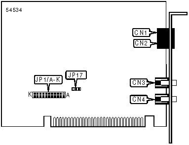
CONNECTIONS | ||||||
|
Function |
Label |
Function |
Label | |||
|
Line out |
CN1 |
Microphone in |
CN3 | |||
|
Line in |
CN2 |
Speaker out |
CN4 | |||
|
USER CONFIGURABLE SETTINGS | ||
|
Setting |
Label |
Position |
|
Factory configured - do not alter |
JP17 |
Unidentified |
|
SERIAL PORT ADDRESS | ||
|
Setting |
JP1/A |
JP1/B |
|
COM1 (3F8h) |
On |
On |
|
COM2 (2F8h) |
On |
Off |
|
COM3 (3E8h) |
Off |
On |
|
í COM4 (2E8h) |
Off |
Off |
|
INTERRUPT SELECTION | |||||
|
IRQ |
JP1/C |
JP1/D |
JP1/E |
JP1/F |
JP1/G |
|
í 3 |
Closed |
Open |
Open |
Open |
Open |
|
4 |
Open |
Closed |
Open |
Open |
Open |
|
5 |
Open |
Open |
Closed |
Open |
Open |
|
7 |
Open |
Open |
Open |
Closed |
Open |
|
9 |
Open |
Open |
Open |
Open |
Closed |
|
10 |
Open |
Open |
Open |
Open |
Open |
|
11 |
Open |
Open |
Open |
Open |
Open |
|
12 |
Open |
Open |
Open |
Open |
Open |
|
15 |
Open |
Open |
Open |
Open |
Open |
|
INTERRUPT SELECTION CONTINUED | ||||
|
IRQ |
JP1/H |
JP1/I |
JP1/J |
JP1/K |
|
í 3 |
Open |
Open |
Open |
Open |
|
4 |
Open |
Open |
Open |
Open |
|
5 |
Open |
Open |
Open |
Open |
|
7 |
Open |
Open |
Open |
Open |
|
9 |
Open |
Open |
Open |
Open |
|
10 |
Closed |
Open |
Open |
Open |
|
11 |
Open |
Closed |
Open |
Open |
|
12 |
Open |
Open |
Closed |
Open |
|
15 |
Open |
Open |
Open |
Closed |
|
SUPPORTED COMMAND SET |
|
Basic AT Commands |
|
AT, ‘+++’, A/ |
|
A, B, E, H, M, O, P, Q, S, T, V, X, Y, Z |
|
&C, &M, &P, &Q, &R, &W, &Y, &Z |
|
Extended AT Commands |
|
\A, \G, \K, \N, \V, |
|
%C, %E, %L, %Q, %7, %8 |
|
S Registers |
|
S0, S1, S2, S3, S4, S5, S6, S7, S8, S9, S10, S11, S12, S16, S18, S21, S24, S25, S29, S30, S31, |
|
S32, S33, S38, S91, S92, S201 |
|
Special Commands |
|
+MS?, +H, "V, -K, _SEC, #CLS, #MFR, #MDL, #REV, #VBQ, #VCI |
|
#VSD, #VRX, #VSK |
|
Note: See MHI Help File for full command documentation. |
Proprietary AT Command Set
|
AUTO-MODE DETECTION | |
|
Type: |
Configuration |
|
Format: |
AT [cmds] Nn [cmds] |
|
Description: |
Selects various options for the automatic detection and negotiation of protocols during the handshake process if the modem is communicating with a remote modem of dissimilar speed. |
|
Command |
Function |
|
N0 |
Auto-mode detection disabled |
|
N1 |
Auto-mode detection enabled |
|
CONFIGURATION PROFILES | |
|
Type: |
Immediate |
|
Format: |
AT [cmds] &V [cmds] |
|
Description: |
Displays active and stored configuration profiles |
|
Command |
Function |
|
&V1 |
Display last connection status |
|
DATA SET READY (DSR) | |
|
Type: |
Configuration |
|
Format: |
AT [cmds] &Sn [cmds] |
|
Description: |
Selects DSR options |
|
Command |
Function |
|
&S0 |
DSR forced high |
|
&S1 |
DSR high only while modem is connected |
|
DATA TERMINAL READY (DTR) | ||||
|
Type: |
Configuration | |||
|
Format: |
AT [cmds] &Dn [cmds] | |||
|
Description: |
Selects modem response to DTR | |||
Note: The action each variant of &D causes depends on the setting of &Q | ||||
|
&Q Setting |
&D0 |
&D1 |
&D2 | |
|
&Q0, &Q5, &Q6 |
NONE |
Command 3 |
Command 3 | |
|
&Q1, &Q4 |
Command 1 |
Command 3 |
Command 3 | |
|
&Q2, &Q3 |
Command 2 |
Command 2 |
Command 2 | |
|
Command |
Function | |||
|
Command 0 |
Modem does not respond to DTR | |||
|
Command 1 |
Modem goes to command mode after DTR goes is off | |||
|
Command 2 |
Modem goes to command mode and disconnects (hangs up) after DTR goes off; Auto-Answer is disabled. | |||
|
Command 3 |
Modem is initialized after DTR goes off | |||
|
DIAL | |
|
Type: |
Immediate |
|
Format: |
AT [cmds] D<#> [cmds] |
|
Description: |
Dials telephone number according to any modifiers included in the string |
|
Note: |
Any combination of modifiers can be used to produce the desired dial functions in sequence. |
|
Command |
Function |
|
DP |
Pulse dialing enabled |
|
DS=n |
Dial stored telephone number n |
|
DT |
Tone dialing enabled/Pulse dialing disabled |
|
DW |
Dialing resumed following dial tone detection |
|
D, |
Dialing paused for amount of time specified in S8 register |
|
D* |
Dials the star digit on tone dialing mode |
|
D# |
Dials the gate digit on tone dialing mode |
|
D! |
Flash function initiated. Modem commanded to go off-hook for specified time before returning on-hook. |
|
D; |
Modem returned to idle state after dialing. The semicolon can only be placed at the end of the dial command. |
|
FACTORY DEFAULT PROFILE | |
|
Type: |
Configuration |
|
Format: |
AT [cmds] &F [cmds] |
|
Description: |
Sets values in active profile to values found in the default profile |
|
Command |
Function |
|
&F0 |
Restore factory configuration 0 |
|
&F1 |
Restore factory configuration 1 |
|
FLOW CONTROL | |
|
Type: |
Configuration |
|
Format: |
AT [cmds] &Kn [cmds] |
|
Description: |
Enables flow control options |
|
Command |
Function |
|
&K0 |
Flow control disabled |
|
&K3 |
RTS to CTS flow control enabled |
|
&K4 |
XON/XOFF flow control enabled |
|
&K5 |
Transparent XON/XOFF flow control enabled |
|
&K6 |
RTS/CTS & XON/XOFF flow control enabled |
|
GUARD TONE | |
|
Type: |
Configuration |
|
Format: |
AT [cmds] &Gn [cmds] |
|
Description: |
Commands the modem to transmit a guard tone in V.22/V.22bis |
Note: Used primarily for international data transmission | |
|
Command |
Function |
|
&G0 |
Guard tone disabled |
|
&G1 |
Guard tone disabled |
|
&G2 |
1800Hz guard tone enabled |
|
MNP10 - FALLBACK | |
|
Type: |
Configuration |
|
Format: |
AT [cmds] -Qn [cmds] |
|
Note: |
This command is included only for compatibility and performs no function. |
|
MNP10 - LINK NEGOTIATION | |
|
Type: |
Configuration |
|
Format: |
AT [cmds] *Hn [cmds] |
|
Note: |
Included only for compatibility and performs no function |
|
MNP10 - POWER LEVEL ADJUST | |
|
Type: |
Configuration |
|
Format: |
AT [cmds] )Mn [cmds] |
|
Note: |
This command is included only for compatibility and performs no function. |
|
PLUG AND PLAY SERIAL NUMBER | |
|
Type: |
Configuration |
|
Format: |
AT [cmds] %7 [cmds] |
|
Description: |
Sets and stores plug and play serial number. |
|
PLUG AND PLAY VENDOR ID AND PRODUCT NUMBER | |
|
Type: |
Configuration |
|
Format: |
AT [cmds] %8 [cmds] |
|
Description: |
Sets and stores plug and play vendor ID and product number. |
|
REPORT INFORMATION | |
|
Type: |
Immediate |
|
Format: |
AT [cmds] In [cmds] |
|
Description: |
Displays information requested |
|
Command |
Function |
|
I0 |
Reports product code |
|
I1 |
Reports ROM checksum (normally "255") |
|
I2 |
Reports "OK" |
|
I3 |
Reports firmware revision (VX.XXX) |
|
I4 |
Reports OEM defined identifier string |
|
I5 |
Reports country code parameter |
|
I6 |
Reports modem data pump model and internal code revision |
|
I7 |
Reports "255" |
|
SPEAKER VOLUME | |
|
Type: |
Configuration |
|
Format: |
AT [cmds] Ln [cmds] |
|
Description: |
Controls speaker volume |
|
Command |
Function |
|
L0 |
Low volume setting |
|
L1 |
Low volume setting |
|
L2 |
Medium volume setting |
|
L3 |
Highest volume setting |
|
TEST MODES | |
|
Type: |
Immediate |
|
Format: |
AT [cmds] &Tn |
|
Description: |
Selects test options |
|
Command |
Function |
|
&T0 |
End current test |
|
&T1 |
Begin local analog loopback test |
|
&T2 |
Returns ERROR |
|
&T3 |
Begin local digital loopback |
|
&T4 |
Grant remote digital loopback request |
|
&T5 |
Deny remote digital loopback request |
|
&T6 |
Request remote digital loopback |
|
&T7 |
Request remote digital loopback and self-test |
|
&T8 |
Begin local analog loopback and self-test |
|
TONE GENERATOR LENGTH | |
|
Format |
AT [cmds] #VBT=n [cmds] |
|
Default: |
10 |
|
Range: |
0 - 40 |
|
Unit: |
0.1 second |
|
Description: |
Sets the length of DTMF tones that are generated. |
|
Command |
Function |
|
#VBT0 |
Disables the tone generation capability |
|
#VBT1 |
Sets tone duration time to .1 second |
|
TRANSMISSION LEVEL - CELLULAR | |
|
Type: |
Configuration |
|
Format: |
AT [cmds] @Mn [cmds] |
|
Range: |
11-31 |
|
Unit: |
-1dBm |
|
Note: |
This command is included only for compatibility and performs no function. |
|
V.32 - COMPROMISE EQUALIZER | |
|
Type: |
Configuration |
|
Format: |
AT [cmds] :En [cmds] |
|
Note: |
This command is included only for compatibility and performs no function. |
|
V.32 OR V.34 MODULATION | |
|
Type: |
Configuration |
|
Format: |
AT [cmds] "Vn [cmds] |
|
Description: |
Controls modulation for V.32 or V.34 |
|
Command |
Function |
|
"V.32" |
V.32 or V.32bis modulation |
|
"V.34"* |
V.34 modulation |
|
VOICE - DISPLAY COMPRESSION TYPE | |
|
Type: |
Immediate |
|
Format: |
AT [cmds] #VCI? [cmds] |
|
Description: |
Displays the type of compression currently in use. |
|
VOICE - LOCAL SERIAL PORT SPEED | |
|
Type: |
Configuration |
|
Format: |
AT [cmds] #BDR=n [cmds] |
|
Description: |
Sets the speed of the local serial port when in voice mode. |
|
Command |
Function |
|
#BDR=0 |
Autobank selected |
|
#BDR=1 |
Set speed to 2400bps |
|
#BDR=2 |
Set speed to 4800bps |
|
#BDR=4 |
Set speed to 9600bps |
|
#BDR=6 |
Set speed to 14.4Kbps |
|
#BDR=8 |
Set speed to 19.2Kbps |
|
#BDR=12 |
Set speed to 28.8Kbps |
|
#BDR=16 |
Set speed to 38.4Kbps |
|
#BDR=24 |
Set speed to 57.6Kbps |
|
VOICE BUFFER SPACE | |
|
Type: |
Configuration |
|
Format: |
AT [cmds] #VSK=n [cmds] |
|
Default: |
255 |
|
Range: |
0 - 255 |
|
Unit: |
1 byte |
|
Description: |
Sets the amount of data the modem can send into the buffer after the XOFF signal is sent. |
|
VOICE DEVICE | |
|
Type: |
Configuration |
|
Format: |
AT [cmds] #VLS=n [cmds] |
|
Description: |
Selects the I/O device for the DSP chip. |
|
Note: |
This modem may not support all options listed below. The #VLS? Command will display the available options. |
|
Command |
Function |
|
í #VLS=0 |
Telephone line and handset used for voice I/O. |
|
#VLS=1 |
Telephone handset used for voice I/O. |
|
#VLS=2 |
Internal speaker only used for voice I/O. |
|
#VLS=3 |
External microphone only used for voice I/O. |
|
#VLS=4 |
Telephone line and handset used for voice I/O; internal speaker enabled. |
|
VOICE RECEIVE | |
|
Type: |
Configuration |
|
Format: |
AT [cmds] #VRX=n [cmds] |
|
Description: |
Commands the modem to begin receiving voice data. |
|
VOICE RE-RING DETECT TIME | |
|
Type: |
Configuration |
|
Format: |
AT [cmds] #VRA=n [cmds] |
|
Default: |
70 |
|
Range: |
0-255 |
|
Unit: |
10 mS |
|
Description: |
Sets the maximum time the modem will wait for the remote station to ring again before it assumes that it has gone off-hook. |
|
Command |
Function |
|
#VRA=0 |
Ringback goes away timer disabled |
|
VOICE RING DETECT TIME | ||
|
Type: |
Configuration | |
|
Format: |
AT [cmds] #VRN=n [cmds] | |
|
Default: |
Unidentified | |
|
Range: |
Unidentified | |
|
Unit: |
Unidentified | |
|
Description: |
Sets the maximum time the modem will wait for the remote station to ring before it assumes that it went off-hook before it rang. | |
|
Command |
Function | |
|
#VRN=0 |
Disables voice ring detect time | |
|
VOICE SAMPLE QUALITY | ||
|
Type: |
Configuration | |
|
Format: |
AT [cmds] #VBS=n [cmds] | |
|
Description: |
Selects the number of bits per sample that the modem records. | |
|
Note: |
This modem may not support all options listed below. The #VBS? Command will display the available options. | |
|
Command |
Function | |
|
#VBS=2 |
Modem records 2 bits per sample in ADPCM encoding. | |
|
#VBS=3 |
Modem records 3 bits per sample in ADPCM encoding. | |
|
î #VBS=4 |
Modem records 4 bits per sample in ADPCM encoding. | |
S(status) -REGISTERS
|
BIT-MAPPED REGISTER S14 | ||
|
Format: |
AT [cmds] S14=n [cmds] | |
|
Range: |
0-174 | |
|
Unit: |
Bit-mapped | |
|
Description: |
Controls echo, result codes and display, dial mode, and answer/originate mode. | |
|
Bit |
Value |
Function |
|
0 |
0 |
Not used |
|
1 |
0 1 |
Command echo disabled Command echo enabled |
|
2 |
0 1 |
Result codes enabled Result codes disabled |
|
3 |
0 1 |
Display result codes in numeric format Display result codes in verbose format |
|
5 |
0 1 |
Tone dial enabled Pulse dial enabled |
|
6 |
0 |
Not used |
|
7 |
0 1 |
Answer mode enabled Originate mode enabled |
|
BIT-MAPPED REGISTER S19 | ||
|
Format |
AT [cmds] S19=n [cmds] | |
|
Default: |
0, 0, 0, 0 | |
|
Range: |
0-253 | |
|
Unit: |
Bit-mapped | |
|
Description: |
Selects communications protocol, address detection, NRZ mode, and idle indicator. | |
|
Bit |
Value |
Function |
|
1 |
0 1 |
Selects BSC format Selects HDLC format |
|
2 |
0 1 |
Address detection disabled Address detection enabled |
|
3 |
0 1 |
NRZI coding enabled NRZ coding enabled |
|
4 |
0 1 |
Mark idle Flag or sync idle |
|
AUTOSYNC | |
|
Type: |
Register |
|
Format |
AT [cmds] S20=n [cmds] |
|
Default: |
0 |
|
Range: |
0-255 |
|
Unit: |
ASCII |
|
Description: |
Selects the AutoSync HDLC address or BSC sync character |
|
BIT-MAPPED REGISTER S22 | ||
|
Format |
AT [cmds] S22=n [cmds] | |
|
Range: |
0-255 | |
|
Unit: |
Bit-mapped | |
|
Description: |
Controls speaker volume and controls, limits results codes, and pulse dial make/break ratio. | |
|
Bit |
Value |
Function |
|
1, 0 |
00 01 10 11 |
Off volume Low level volume Medium level volume High level volume |
|
3, 2 |
00 01 10 11 |
Speaker off Speaker off on carrier Speaker always on Speaker on during handshake |
|
6 - 4 |
000 100 101 110 111 |
Basic result codes only enabled Basic and connection speed result codes enabled Basic and connection speed result codes and dialtone detection enabled All result codes except dialtone detection enabled All result codes enabled |
|
BIT-MAPPED REGISTER S23 | ||
|
Format |
AT [cmds] S23=n [cmds] | |
|
Range: |
0-189 | |
|
Unit: |
Bit-mapped | |
|
Description: |
Grants/denies remote digital loopback, controls DTE rate and parity, and sets guard tone. | |
|
Bit |
Value |
Function |
|
0 |
0 1 |
Remote digital loopback denied Remote digital loopback allowed |
|
3 - 1 |
000 001 010 011 100 101 110 |
Sets serial port speed to 0-300bps Sets serial port speed to 1200bps Sets serial port speed to 2400bps Sets serial port speed to 4800bps Sets serial port speed to 9600bps Sets serial port speed to 19200bps Sets serial port speed to 38400bps |
|
5, 4 |
00 01 10 11 |
Parity even Space Parity Parity odd Mark or No Parity |
|
7, 6 |
00 01 10 |
Guard tone disabled Guard tone disabled Guard tone 1800Hz enabled |
|
BIT-MAPPED REGISTER S27 | ||
|
Format |
AT [cmds] S27=n [cmds] | |
|
Range: |
0-111 | |
|
Unit: |
Bit-mapped | |
|
Description: |
Selects ITU-T/Bell modes. | |
|
Bit |
Value |
Function |
|
1 |
0 |
Not used |
|
2 |
0 |
Not used |
|
3 |
0 |
Not used |
|
4 |
0 |
Not used |
|
5 |
0 |
Not used |
|
6 |
0 1 |
ITU/T mode Bell mode |
|
BIT-MAPPED REGISTER S28 | ||
|
Format |
AT [cmds] S28=n [cmds] | |
|
Range: |
0-31 | |
|
Unit: |
Bit-mapped | |
|
Description: |
Controls pulse dialing and MNP link speed. | |
|
Bit |
Value |
Function |
|
0 |
0 |
Not used |
|
1 |
0 |
Not used |
|
2 |
0 |
Not used |
|
4, 3 |
00 01 10 11 |
39ms make/61ms break at 10pps 33ms make/67ms break at 10pps 39ms make/61ms break at 20pps 33ms make/67ms break at 20pps |
|
5 |
0 |
Not used |
|
7, 6 |
00 01 10 |
Highest speed 1200bps 4800bps |
|
ERROR CORRECTION NEGOTIATION | |
|
Type: |
Register |
|
Format |
AT [cmds] S36=n [cmds] |
|
Description: |
Selects the action of the modem if it fails to connect with the error-correction protocol set in &Q. |
|
Command |
Function |
|
S36=0 |
Hang up |
|
S36=1 |
Attempt a direct connection |
|
S36=3 |
Attempt a buffered connection |
|
S36=4 |
Attempt a connection at MNP2-4; if that fails, hang up. |
|
S36=5 |
Attempt a connection at MNP2-4; if that fails, attempt a direct connection. |
|
S36=7 |
Attempt a connection at MNP2-4; if that fails, attempt a buffered connection. |
|
DCE LINE SPEED | |
|
Type: |
Register |
|
Format |
AT [cmds] S37=n [cmds] |
|
Description: |
Sets the maximum allowable data exchange rate attempted during handshake process. |
|
Command |
Function |
|
S37=0 |
Auto-detect mode |
|
S37=1-3 |
300bps |
|
S37=5 |
V.22 1200bps |
|
S37=6 |
V.22bis 2400bps |
|
S37=7 |
V.23 |
|
S37=8 |
V.32bis or V.32 4800bps |
|
S37=9 |
V.32bis or V.32 9600bps |
|
S37=10 |
V.32bis 12000bps |
|
S37=11 |
V.32bis 14400bps |
|
S37=12 |
V.32bis 7200bps |
|
S37=15 |
V.FC 14400 |
|
S37=16 |
V.FC 16800 |
|
S37=17 |
V.FC 19200 |
|
S37=18 |
V.FC 21600 |
|
S37=19 |
V.FC 24000 |
|
S37=20 |
V.FC 24600 |
|
S37=21 |
V.FC 28800 |
|
FLOW CONTROL | |
|
Type: |
Register |
|
Format |
AT [cmds] S39? [cmds] |
|
Description: |
Displays the current flow control |
|
Value |
Meaning |
|
0 |
Flow control disabled |
|
3 |
RTS/CTS flow control enabled (&K3, Default) |
|
4 |
XON/XOFF flow control enabled (&K4) |
|
5 |
Transparent XON/XOFF flow control enabled (&K5) |
|
6 |
Both methods (&K6) |
|
BIT-MAPPED REGISTER S40 | ||
|
Format |
AT [cmds] S40=n [cmds] | |
|
Range: |
0-255 | |
|
Unit: |
Bit-mapped | |
|
Description: |
Controls power level and break handling; selects MNP extended services, link negotiation, and block size. | |
|
Bit |
Value |
Function |
|
0, 1 |
00 01 10 |
MNP Extended Services disabled MNP Extended Services enabled MNP Extended Services enabled |
|
2 |
0 1 |
Power level adjustment enabled Power level adjustment disabled |
|
4 |
0 |
Not used |
|
5, 3 |
000 001 010 011 100 101 |
AT\K0 AT\K1 AT\K2 AT\K3 AT\K4 AT\K5 |
|
7, 6 |
00 01 10 11 |
MNP block size is 64 characters MNP block size is 128 characters MNP block size is 192 characters MNP block size is 256 characters |
|
BIT-MAPPED REGISTER S41 | ||
|
Format |
AT [cmds] S41=n [cmds] | |
|
Range: |
0-31 | |
|
Unit: |
Bit-mapped | |
|
Description: |
Selects compression, auto-retrain, flow control, MNP mode, and fallback mode. | |
|
Bit |
Value |
Function |
|
1, 0 |
00 01 10 11 |
Data compression disabled MNP5 enabled V.42bis enabled MNP5 and V.42bis enabled |
|
6, 2 |
00 01 10 |
Auto-retrain disabled Auto-retrain enabled Fallback/Fall forward enabled |
|
3 |
0 1 |
Flow control disabled Flow control enabled |
|
4 |
0 1 |
Stream mode for MNP Block mode for MNP |
|
5 |
0 |
Not used |
|
6 |
0 |
Not used |
|
7 |
0 1 |
Fallback disabled Fallback enabled |
|
ERROR CORRECTION/COMPRESSION | |||
|
Type: |
Register | ||
|
Format: |
AT [cmds] S46=n [cmds] | ||
|
Description: |
Selects active error correction and compression protocols | ||
|
Command |
Function | ||
|
S46=136 |
LAP-M only, no compression | ||
|
S46=138 |
LAP-M with V.42bis data compression | ||
|
FEATURE NEGOTIATION OPTIONS | |||
|
Type: |
Register | ||
|
Format: |
AT [cmds] S48=n [cmds] | ||
|
Description: |
Selects active error correction and compression protocols | ||
|
Command |
Function | ||
|
S48=0 |
Detection negotiation disabled, XID negotiation disabled | ||
|
S48=7 |
Detection negotiation and XID negotiation enabled | ||
|
S48=128 |
Fall-back to options set in S36 | ||
|
BREAK OPTIONS | |
|
Type: |
Register |
|
Format |
AT [cmds] S82=n [cmds] |
|
Note: |
This register for compatibility purposes only and performs no function. |
|
CONNECTION FAILURE CODES | |
|
Type: |
Register |
|
Format |
AT [cmds] S86? [cmds] |
|
Description: |
Reports codes which correspond to the possible causes of a connection failure |
|
Value |
Meaning |
|
0 |
Normal hang up |
|
4 |
Carrier signal lost |
|
5 |
No error-control detected for remote modem during feature negotiation |
|
9 |
No common protocol found |
|
12 |
No failure - remote modem disconnected normally |
|
13 |
Remote modem failed to respond after 10 re-transmissions same message |
|
14 |
Violation of negotiated protocol caused failure |
|
CELLULAR TRANSMIT LEVEL | ||
|
Type: |
Register | |
|
Format |
AT [cmds] S201=n [cmds] | |
|
Range: |
0-255 | |
|
Unit: |
Bit-mapped | |
|
Description: |
Works in combination with the @Mn and :En commands to support cellular connection. | |
|
Bit |
Value |
Function |
|
0 - 4 |
@Mn |
Initial power level setting |
|
5 |
:En |
Compromise equalizer enable command |