STANDARD MICROSYSTEMS CORPORATION
ARCNET PC250
|
NIC Type |
Arcnet |
|
Chipset |
SMC 9026, 9032 |
|
Network Transfer Rate |
2.5Mbps |
|
Data Bus |
8-bit ISA |
|
Topology |
Linear Bus/Star |
|
Wire Type |
Unshielded twisted pair |
|
Boot ROM |
Available |
|
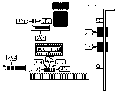
CONNECTIONS | |||
|
Function |
Label |
Function |
Label |
|
Unshielded twisted pair connector |
J1 |
Unshielded twisted pair connector |
J2 |
|
INTERRUPT | |||||
|
Setting |
JP3 |
JP4 |
JP5 |
JP6 |
JP7 |
|
IRQ2 |
Closed |
Open |
Open |
Open |
Open |
|
IRQ3 |
Open |
Closed |
Open |
Open |
Open |
|
IRQ4 |
Open |
Open |
Closed |
Open |
Open |
|
IRQ5 |
Open |
Open |
Open |
Closed |
Open |
|
IRQ7 |
Open |
Open |
Open |
Open |
Closed |
|
EXTENDED RANGE CONFIGURATION | ||||
|
Response Time |
Recon Time |
JP1 |
JP2 | |
| » |
75.7 uS |
840 mS |
Open |
Open |
|
283.4 uS |
1.68 S |
Closed |
Open | |
|
561.8 uS |
1.68 S |
Open |
Closed | |
|
1.1186 mS |
1.68 S |
Closed |
Closed | |
|
Note:This setting should only be changed when the length of the ArcNet segments exceed 6000 meters. | ||||
|
NODE ADDRESS | ||||||||
|
Setting |
SW1/1 |
SW1/2 |
SW1/3 |
SW1/4 |
SW1/5 |
SW1/6 |
SW1/7 |
SW1/8 |
|
1 |
Off |
On |
On |
On |
On |
On |
On |
On |
|
2 |
On |
Off |
On |
On |
On |
On |
On |
On |
|
3 |
Off |
Off |
On |
On |
On |
On |
On |
On |
|
4 |
On |
On |
Off |
On |
On |
On |
On |
On |
|
5 |
Off |
On |
Off |
On |
On |
On |
On |
On |
|
250 |
On |
Off |
On |
Off |
Off |
Off |
Off |
Off |
|
251 |
Off |
Off |
On |
Off |
Off |
Off |
Off |
Off |
|
252 |
On |
On |
Off |
Off |
Off |
Off |
Off |
Off |
|
253 |
Off |
On |
Off |
Off |
Off |
Off |
Off |
Off |
|
254 |
On |
Off |
Off |
Off |
Off |
Off |
Off |
Off |
|
Note: A total of 254 node address settings are available. The switches are a binary representation of the decimal node addresses. SW1/8 is the Most Significant Bit and switch SW1/1 is the Least Significant Bit. The switches have the following decimal values: SW1/8=128, SW1/7=64, SW1/6=32, SW1/5=16, SW1/4=8, SW1/3=4, SW1/2=2, SW1/1=1. Turn off the switches and add the values of the switches that are off to obtain the correct node ID. (Off=1, On=0)Node addresses 0 and 255 are reserved and should not be used. | ||||||||
|
BASE I/O ADDRESS | |||||||
|
Setting |
SW1/1 |
SW1/2 |
SW1/3 |
SW1/4 |
SW1/5 |
SW1/6 | |
|
000h |
On |
On |
On |
On |
On |
On | |
|
010h |
On |
On |
On |
On |
On |
Off | |
|
020h |
On |
On |
On |
On |
Off |
On | |
|
030h |
On |
On |
On |
On |
Off |
Off | |
|
040h |
On |
On |
On |
Off |
On |
On | |
| » |
2E0h |
Off |
On |
Off |
Off |
Off |
On |
|
3B0h |
Off |
Off |
Off |
On |
Off |
Off | |
|
3C0h |
Off |
Off |
Off |
Off |
On |
On | |
|
3D0h |
Off |
Off |
Off |
Off |
On |
Off | |
|
3E0h |
Off |
Off |
Off |
Off |
Off |
On | |
|
3F0h |
Off |
Off |
Off |
Off |
Off |
Off | |
|
Note: A total of 64 base address settings are available. The switches are a binary representation of the decimal memory addresses. SW1/1 is the Most Significant Bit and switch SW1/6 is the Least Significant Bit. The switches have the following decimal values: SW1/1=512, SW1/2=256, SW1/3=128, SW1/4=64, SW1/5=32, SW1/6=16. Turn off the switches and add the values of the switches that are off to obtain the correct memory address. (Off=1, On=0) | |||||||
|
SHARED RAM ADDRESS | ||||
|
Setting |
SW2/7 |
SW2/8 |
SW2/9 |
SW2/10 |
|
00000h |
Off |
Off |
Off |
Off |
|
10000h |
Off |
Off |
Off |
On |
|
20000h |
Off |
Off |
On |
Off |
|
30000h |
Off |
Off |
On |
On |
|
40000h |
Off |
On |
Off |
Off |
|
50000h |
Off |
On |
Off |
On |
|
60000h |
Off |
On |
On |
Off |
|
70000h |
Off |
On |
On |
On |
|
80000h |
On |
Off |
Off |
Off |
|
90000h |
On |
Off |
Off |
On |
|
A0000h |
On |
Off |
On |
Off |
|
B0000h |
On |
Off |
On |
On |
|
C0000h |
On |
On |
Off |
Off |
|
D0000h |
On |
On |
Off |
On |
|
E0000h |
On |
On |
On |
Off |
|
F0000h |
On |
On |
On |
On |