EXOS
201
|
NIC Type |
Ethernet |
|
Transfer Rate |
10Mbps |
|
Data Bus |
Multibus |
|
Topology |
Linear bus |
|
Wiring Type |
AUI transceiver via DB-15 on sub-connector |
|
Boot ROM |
Available (in firmware) |
|
FACTORY CONFIGURED | |
|
Jumper |
Setting |
|
J2 |
Closed |
|
J3 |
Open |
|
J9 |
Open |
|
J10 |
Closed |
|
J12 |
Open |
|
J61 |
Closed |
|
ONBARD BUFFER RAM | ||
|
Size |
J4 |
J7 |
|
128KB |
Open |
Open |
|
256KB |
Open |
Closed |
|
512KB |
Closed |
Open |
|
CARRIER SENSE CONFIGURATION | ||
|
Setting |
J5 | |
| » |
Carrier sense enabled |
Open |
|
Carrier sense disabled |
Closed | |
|
Note:Carrier sense should be disabled when using a broad-band transceiver. | ||
|
BOOT ROM | |
|
Setting |
J6 |
|
Enabled |
Closed |
|
Disabled |
Open |
|
SIGNAL QUALITY CONFIGURATION | ||
|
Setting |
J11 | |
| » |
Signal quality check enabled |
Closed |
|
Signal quality check disabled |
Open | |
|
Note:Signal quality checking should be disabled in any Ethernet version 1 installation. | ||
|
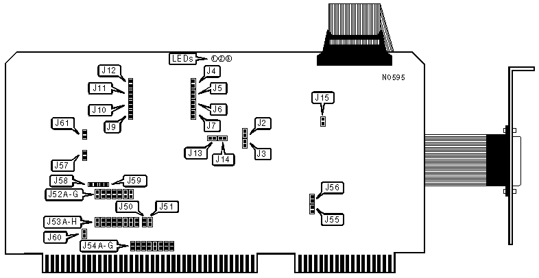
MULTIBUS I/O (SLAVE) ACCESS CONFIGURATION |
|
The EXOS 201 supports two simultaneous I/O ports, labeled port A and port B. In addition, the 201 supports either 8-bit or 16-bit memory addressing. When in 16-bit addressing mode, the port A address is selectable via jumper J52 & J53. Jumper J52A-G defines bits 1-7 of the memory address respectively, and J53A-H defines bits 8-15 respectively (when a jumper is closed, the bit that it corresponds to is set to 1; when open, the bit is set to 0.). For expample, if JP52A is closed, and JP52B-G & JP53A-H are open, the memory address selected is 0001h. When in 8-bit addressing mode, JP52A-G select bits 1-7 respectively, and JP53 is inactive. Regardless of the memory addressing mode, port B will always be located 1 byte above port A's address (e.g. Port A = 0001h, Port B = 0002h). Bit 0 is always set to 0 for port A, and 1 for port B. (Open=0, closed=1) |
|
MULTIBUS MEMORY ADDRESSING METHOD | ||
|
Memory Address |
J50 |
J51 |
|
8-bit memory addressing |
Open |
Closed |
|
16-bit memory addressing |
Closed |
Open |
|
44-PIN ISBX CONNECTOR CONFIGURATION |
|
The iSBX connector (IEEE P969 specification), is included for daughterboard options. There are two jumper-selectable interrupt lines (J13 and J14) which should be left open unless an optional daugherboard is installed. If a daughterboard is installed, one jumper or the other must be closed, but not both. JP13 closed selects IR0, JP14 selects IR1. |
|
WATCHDOG TIMER CONFIGURATION | |
|
Setting |
J15 |
|
Watchdog timer enabled |
Open |
|
Watchdog timer disabled |
Closed |
|
MULTIBUS INTERRUPT ACCESS | ||||||||
|
INT |
J54A |
J54B |
J54C |
J54D |
J54E |
J54F |
J54G |
J54H |
|
0 |
Open |
Open |
Open |
Open |
Open |
Open |
Open |
Closed |
|
1 |
Open |
Open |
Open |
Open |
Open |
Open |
Closed |
Open |
|
2 |
Open |
Open |
Open |
Open |
Open |
Closed |
Open |
Open |
|
3 |
Open |
Open |
Open |
Open |
Closed |
Open |
Open |
Open |
|
4 |
Open |
Open |
Open |
Closed |
Open |
Open |
Open |
Open |
|
5 |
Open |
Open |
Closed |
Open |
Open |
Open |
Open |
Open |
|
6 |
Open |
Closed |
Open |
Open |
Open |
Open |
Open |
Open |
|
7 |
Closed |
Open |
Open |
Open |
Open |
Open |
Open |
Open |
|
USER PROGRAMMABLE EPROM TYPE | ||
|
Type |
J55 |
J56 |
|
27128 |
Closed |
Open |
|
27256 |
Open |
Closed |
|
None |
Open |
Open |
|
MULTIBUS PRIORITY RESOLUTION METHOD | ||
|
Resolution Scheme |
J57 | |
| » |
Enabled |
Closed |
|
Disabled |
Open | |
|
BUS ARBITRATION | |||
|
Setting |
J58 |
J59 | |
| » |
Disabled |
Open |
Closed |
|
Enabled |
Closed |
Open | |
|
CLOCK CONFIGURATION | |
|
Setting |
J60 |
|
/CCLK and /BCLK bus driven |
Open |
|
/CCLK and /BCLK card driven |
Closed |
|
DIAGNOSTIC LED(S) | ||
|
LED |
Status |
Condition |
|
1 |
On |
Performing power on self tests |
|
1 |
Flashing |
Waiting for host or network initialization |
|
1 |
Off |
Card succesfully inserted into network |
|
2 |
On |
Data is being transmitted |
|
2 |
Off |
Data is not being transmitted |
|
3 |
On |
Attempted access to non-existant memory location on multibus |
|
3 |
Pulsing |
Multibus cycle in progress |
|
3 |
Off |
No multibus cycle in progress |