ADDTRON TECHNOLOGY COMPANY, LTD.
ARC-210 VER. 2
|
NIC Type |
ARCnet |
|
Transfer Rate |
2.5Mbps |
|
Data Bus |
16-bit ISA |
|
Topology |
Star Linear bus |
|
Wiring Type |
RG-62A/U 93ohm coaxial |
|
Boot ROM |
Available |
|
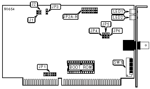
BOOT ROM |
||
|
Mode |
JP1 |
|
|
» |
Disabled |
Pins 2 & 3 closed |
|
|
Enabled |
Pins 1 & 2 closed |
|
CONNECTIONS |
|
|
Purpose |
Location |
|
Connection for LED1 |
J1 |
|
Connection for LED2 |
J2 |
|
DIAGNOSTIC LED(S) |
|||
|
LED |
Color |
Status |
Condition |
|
LED1 |
Green |
On |
Data is being transmitted or received. |
|
LED1 |
Green |
Off |
Data is not being transmitted or received. |
|
LED1 |
Green |
Blinking |
Network connection is broken |
|
LED2 |
Red |
On |
Card is being accessed by the host computer |
|
LED2 |
Red |
Off |
Card is not being accessed by the host computer |
|
FACTORY CONFIGURED SETTINGS |
|
|
Jumper |
JP1 |
|
JP4 |
Pins 2 & 3 closed |
|
JP5 |
Pins 2 & 3 closed |
|
JP6 |
Pins 2 & 3 closed |
|
I/O BASE ADDRESS |
||||
|
Address |
JP2/F |
JP2/G |
JP2/H |
|
|
» |
2E0h - 2EFh |
Pins 1 & 2 closed |
Pins 2 & 3 closed |
Pins 1 & 2 closed |
|
|
260h - 26Fh |
Pins 1 & 2 closed |
Pins 1 & 2 closed |
Pins 1 & 2 closed |
|
|
290h - 29Fh |
Pins 2 & 3 closed |
Pins 1 & 2 closed |
Pins 1 & 2 closed |
|
|
2F0h - 2FFh |
Pins 2 & 3 closed |
Pins 2 & 3 closed |
Pins 1 & 2 closed |
|
|
300h - 30Fh |
Pins 1 & 2 closed |
Pins 1 & 2 closed |
Pins 2 & 3 closed |
|
|
350h - 35Fh |
Pins 2 & 3 closed |
Pins 1 & 2 closed |
Pins 2 & 3 closed |
|
|
380h - 38Fh |
Pins 1 & 2 closed |
Pins 2 & 3 closed |
Pins 2 & 3 closed |
|
|
3E0h - 3EFh |
Pins 2 & 3 closed |
Pins 2 & 3 closed |
Pins 2 & 3 closed |
|
INTERRUPT REQUEST |
||||||||
|
IRQ |
JP1/1 |
JP1/2 |
JP1/3 |
JP1/4 |
JP1/5 |
JP1/6 |
JP1/7 |
|
|
» |
2 |
Closed |
Open |
Open |
Open |
Open |
Open |
Open |
|
|
3 |
Open |
Closed |
Open |
Open |
Open |
Open |
Open |
|
|
4 |
Open |
Open |
Closed |
Open |
Open |
Open |
Open |
|
|
5 |
Open |
Open |
Open |
Closed |
Open |
Open |
Open |
|
|
10 |
Open |
Open |
Open |
Open |
Closed |
Open |
Open |
|
|
11 |
Open |
Open |
Open |
Open |
Open |
Closed |
Open |
|
|
12 |
Open |
Open |
Open |
Open |
Open |
Open |
Closed |
|
NODE ADDRESS |
||||||||
|
Node |
SW1/1 |
SW1/2 |
SW1/3 |
SW1/4 |
SW1/5 |
SW1/6 |
SW1/7 |
SW1/8 |
|
1 |
Off |
On |
On |
On |
On |
On |
On |
On |
|
2 |
On |
Off |
On |
On |
On |
On |
On |
On |
|
3 |
Off |
Off |
On |
On |
On |
On |
On |
On |
|
4 |
On |
On |
Off |
On |
On |
On |
On |
On |
|
251 |
Off |
Off |
On |
Off |
Off |
Off |
Off |
Off |
|
252 |
On |
On |
Off |
Off |
Off |
Off |
Off |
Off |
|
253 |
Off |
On |
Off |
Off |
Off |
Off |
Off |
Off |
|
254 |
On |
Off |
Off |
Off |
Off |
Off |
Off |
Off |
|
255 |
Off |
Off |
Off |
Off |
Off |
Off |
Off |
Off |
|
Note: Node address 0 is used for messaging between nodes and must not be used. A total of 255 node address settings are available. The switches are a binary representation of the decimal node addresses. Switch 1 is the Least Significant Bit and switch 8 is the Most Significant Bit. The switches have the following decimal values: switch 1=1, 2=2, 3=4, 4=8, 5=16, 6=32, 7=64, 8=128. Turn Off the switches and add the values of the Off switches to obtain the correct node address. (On=0, Off=1) |
||||||||
|
BASE MEMORY ADDRESS AND BOOR ROM ADDRESS |
||||||
|
Base Address |
Boot ROM Address |
JP2A |
JP2B |
JP2C |
JP2D |
JP2E |
|
D0000h - D07FFh |
D2000h - D3FFFh |
Pins 1 & 2 |
Pins 1 & 2 |
Pins 2 & 3 |
Pins 2 & 3 |
Pins 1 & 2 |
|
C0000h - C07FFh |
C2000h - C3FFFh |
Pins 1 & 2 |
Pins 1 & 2 |
Pins 1 & 2 |
Pins 1 & 2 |
Pins 1 & 2 |
|
C0800h - C0FFFh |
C2000h - C3FFFh |
Pins 2 & 3 |
Pins 1 & 2 |
Pins 1 & 2 |
Pins 1 & 2 |
Pins 1 & 2 |
|
C1000h - C17FFh |
C2000h - C3FFFh |
Pins 1 & 2 |
Pins 2 & 3 |
Pins 1 & 2 |
Pins 1 & 2 |
Pins 1 & 2 |
|
C1800h - C1FFFh |
C2000h - C3FFFh |
Pins 2 & 3 |
Pins 2 & 3 |
Pins 1 & 2 |
Pins 1 & 2 |
Pins 1 & 2 |
|
C4000h - C47FFh |
C6000h - C7FFFh |
Pins 1 & 2 |
Pins 1 & 2 |
Pins 2 & 3 |
Pins 1 & 2 |
Pins 1 & 2 |
|
C4800h - C4FFFh |
C6000h - C7FFFh |
Pins 2 & 3 |
Pins 1 & 2 |
Pins 2 & 3 |
Pins 1 & 2 |
Pins 1 & 2 |
|
C5000h - C57FFh |
C6000h - C7FFFh |
Pins 1 & 2 |
Pins 2 & 3 |
Pins 2 & 3 |
Pins 1 & 2 |
Pins 1 & 2 |
|
C5800h - C5FFFh |
C6000h - C7FFFh |
Pins 2 & 3 |
Pins 2 & 3 |
Pins 2 & 3 |
Pins 1 & 2 |
Pins 1 & 2 |
|
CC000h - CC7FFh |
CE000h - CFFFFh |
Pins 1 & 2 |
Pins 1 & 2 |
Pins 1 & 2 |
Pins 2 & 3 |
Pins 1 & 2 |
|
CC800h - CCFFFh |
CE000h - CFFFFh |
Pins 2 & 3 |
Pins 1 & 2 |
Pins 1 & 2 |
Pins 2 & 3 |
Pins 1 & 2 |
|
CD000h - CD7FFh |
CE000h - CFFFFh |
Pins 1 & 2 |
Pins 2 & 3 |
Pins 1 & 2 |
Pins 2 & 3 |
Pins 1 & 2 |
|
CD800h - CDFFFh |
CE000h - CFFFFh |
Pins 2 & 3 |
Pins 2 & 3 |
Pins 1 & 2 |
Pins 2 & 3 |
Pins 1 & 2 |
|
D0800h - D0FFFh |
D2000h - D3FFFh |
Pins 2 & 3 |
Pins 1 & 2 |
Pins 2 & 3 |
Pins 2 & 3 |
Pins 1 & 2 |
|
D1000h - D17FFh |
D2000h - D3FFFh |
Pins 1 & 2 |
Pins 2 & 3 |
Pins 2 & 3 |
Pins 2 & 3 |
Pins 1 & 2 |
|
D1800h - D1FFFh |
D2000h - D3FFFh |
Pins 2 & 3 |
Pins 2 & 3 |
Pins 2 & 3 |
Pins 2 & 3 |
Pins 1 & 2 |
|
D4000h - D47FFh |
D6000h- D7FFFh |
Pins 1 & 2 |
Pins 1 & 2 |
Pins 1 & 2 |
Pins 1 & 2 |
Pins 2 & 3 |
|
D4800h - D4FFFh |
D6000h - D7FFFh |
Pins 2 & 3 |
Pins 1 & 2 |
Pins 1 & 2 |
Pins 1 & 2 |
Pins 2 & 3 |
|
D5000h - D57FFh |
D6000h - D7FFFh |
Pins 1 & 2 |
Pins 2 & 3 |
Pins 1 & 2 |
Pins 1 & 2 |
Pins 2 & 3 |
|
D5800h - D5FFFh |
D6000h - D7FFFh |
Pins 2 & 3 |
Pins 2 & 3 |
Pins 1 & 2 |
Pins 1 & 2 |
Pins 2 & 3 |
|
D8000h - D87FFh |
DA000h - DBFFFh |
Pins 1 & 2 |
Pins 1 & 2 |
Pins 2 & 3 |
Pins 1 & 2 |
Pins 2 & 3 |
|
D8800h - D8FFFh |
DA000h - DBFFFh |
Pins 2 & 3 |
Pins 1 & 2 |
Pins 2 & 3 |
Pins 1 & 2 |
Pins 2 & 3 |
|
D9000h - D97FFh |
DA000h - DBFFFh |
Pins 1 & 2 |
Pins 2 & 3 |
Pins 2 & 3 |
Pins 1 & 2 |
Pins 2 & 3 |
|
D9800h - D9FFFh |
DA000h - DBFFFh |
Pins 2 & 3 |
Pins 2 & 3 |
Pins 2 & 3 |
Pins 1 & 2 |
Pins 2 & 3 |
|
DC000h - DC7FFh |
DE000h - DFFFFh |
Pins 1 & 2 |
Pins 1 & 2 |
Pins 1 & 2 |
Pins 2 & 3 |
Pins 2 & 3 |
|
DC800h - DCFFFh |
DE000h - DFFFFh |
Pins 2 & 3 |
Pins 1 & 2 |
Pins 1 & 2 |
Pins 2 & 3 |
Pins 2 & 3 |
|
DD000h - DD7FFh |
DE000h - DFFFFh |
Pins 1 & 2 |
Pins 2 & 3 |
Pins 1 & 2 |
Pins 2 & 3 |
Pins 2 & 3 |
|
DD800h - DDFFFh |
DE000h - DFFFFh |
Pins 2 & 3 |
Pins 2 & 3 |
Pins 1 & 2 |
Pins 2 & 3 |
Pins 2 & 3 |
|
E0000h - E07FFh |
E2000h - E3FFFh |
Pins 1 & 2 |
Pins 1 & 2 |
Pins 2 & 3 |
Pins 2 & 3 |
Pins 2 & 3 |
|
E0800h - E0FFFh |
E2000h - E3FFFh |
Pins 2 & 3 |
Pins 1 & 2 |
Pins 2 & 3 |
Pins 2 & 3 |
Pins 2 & 3 |
|
E1000h - E17FFh |
E2000h - E3FFFh |
Pins 1 & 2 |
Pins 2 & 3 |
Pins 2 & 3 |
Pins 2 & 3 |
Pins 2 & 3 |
|
E1800h - E1FFFh |
E2000h - E3FFFh |
Pins 2 & 3 |
Pins 2 & 3 |
Pins 2 & 3 |
Pins 2 & 3 |
Pins 2 & 3 |
|
Note:Pins designated should be in the closed position. |
||||||