ZF MICROSYSTEMS, INC.
SBX/386
|
Processor |
80386SX |
|
Processor Speed |
33MHz |
|
Chip Set |
Unidentified |
|
Video Chip Set |
None |
|
Maximum Onboard Memory |
16MB |
|
Maximum Video Memory |
None |
|
Cache |
None |
|
BIOS |
Unidentified |
|
Dimensions |
254mm x 114mm |
|
I/O Options |
Floppy drive interface, IDE interface, parallel port, serial ports (2), VGA port, PC104 connectors (2), solid state disk |
|
NPU Options |
None |
|
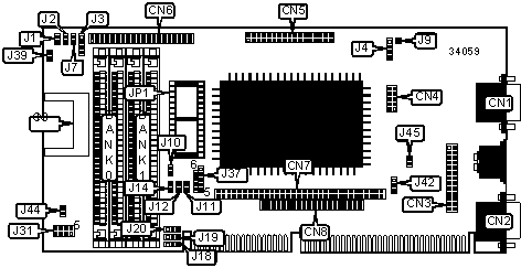
CONNECTIONS | |||
|
Purpose |
Location |
Purpose |
Location |
|
VGA port |
CN1 |
Monitor power input connector |
J1 |
|
Serial port 1 |
CN2 |
IDE interface LED |
J2 |
|
Parallel port |
CN3 |
Speaker |
J3 |
|
Serial port 2 |
CN4 |
External battery |
J4 |
|
Floppy drive interface |
CN5 |
Keylock |
J7 |
|
IDE interface |
CN6 |
Power connector |
J31 |
|
PC104 connector |
CN7 |
Reset switch |
J39 |
|
PC104 connector |
CN8 |
Expansion socket |
JP1 |
|
Solid state disk |
CN9 | ||
|
USER CONFIGURABLE SETTINGS | |||
|
Function |
Label |
Position | |
|
» |
Factory configured - do not alter |
J9 |
Unidentified |
|
» |
BIOS disabled |
J10 |
Open |
|
BIOS enabled |
J10 |
Closed | |
|
VGA IRQ select IRQ9 |
J42 |
Pins 2 & 3 closed | |
|
VGA IRQ select IRQ7 |
J42 |
Pins 1 & 2 closed | |
|
» |
SanDisk master/slave select master |
J44 |
Closed |
|
SanDisk master/slave select slave |
J44 |
Open | |
|
» |
Monitor type select non interlaced |
J45 |
Open |
|
Monitor type select interlaced |
J45 |
Closed | |
|
DRAM CONFIGURATION | ||
|
Size |
Bank 0 |
Bank 1 |
|
2MB |
(2) 1M x 9 |
None |
|
4MB |
(2) 1M x 9 |
(2) 1M x 9 |
|
8MB |
(2) 4M x 9 |
None |
|
10MB |
(2) 4M x 9 |
(2) 1M x 9 |
|
16MB |
(2) 4M x 9 |
(2) 4M x 9 |
|
Note: Board also accepts x 8 SIMMs. | ||
|
EXPANSION SOCKET SELECTION | |||
|
Type |
Device |
Size |
J37 |
|
EPROM |
27C256 |
32KB |
6 & 7, 8 & 9 |
|
EPROM |
27C512 |
64KB |
3 & 7, 8 & 9 |
|
EPROM |
27C010 |
128KB |
2 & 6, 3 & 7, 4 & 5, 8 & 9 |
|
Flash BIOS |
28F256A |
32KB |
1 & 2, 4 & 5, 8 & 9 |
|
Flash BIOS |
28F512 |
64KB |
1 & 2, 4 & 5, 3 & 7 8 & 9 |
|
Flash BIOS |
28F010 |
128KB |
1 & 2, 4 & 5, 3 & 7 8 & 9 |
|
Flash BIOS |
AM29F020 |
128KB |
4 & 5, 3 & 7 8 & 9 |
|
NVRAM |
DS1225Y |
8KB |
5 & 9 |
|
NVRAM |
DS1230 |
32KB |
5 & 9, 7 & 8 |
|
NVRAM |
DS1235Y |
32KB |
5 & 9, 7 & 8 |
|
NVRAM |
DS1630 |
32KB |
5 & 9, 7 & 8 |
|
NVRAM |
DS1245Y |
128KB |
3 & 4, 5 & 9, 7 & 8 |
|
NVRAM |
DS1645Y |
128KB |
3 & 7, 4 & 5, 8 & 9 |
|
NVRAM |
BQ4010Y |
8KB |
5 & 9 |
|
NVRAM |
BQ4011Y |
32KB |
5 & 9, 7 & 8 |
|
NVRAM |
BQ4013Y |
128KB |
3 & 4, 5 & 9, 7 & 8 |
|
Note: Pins designated should be in the closed position. | |||
|
BIOS SELECTION | |||||
|
Size |
Address |
J11 |
J12 |
J14 | |
| » |
Disabled |
N/A |
Closed |
Closed |
Closed |
|
16KB |
DC000h |
Closed |
Closed |
Open | |
|
32KB |
D8000h |
Open |
Open |
Closed | |
|
64KB |
D0000h |
Closed |
Open |
Open | |
|
80KB |
CC000h |
Open |
Closed |
Closed | |
|
96KB |
C8000h |
Open |
Closed |
Open | |
|
112KB |
C4000h |
Open |
Open |
Closed | |
|
128KB |
C0000h |
Open |
Open |
Open | |
|
WATCHDOG TIMER SELECTION | |||
|
Type |
J18 |
J19 |
J20 |
|
Watchdog timer |
Pins 1 & 2 closed |
Pins 1 & 2 closed |
Pins 1 & 2 closed |
|
Power fail |
Pins 2 & 3 closed |
Pins 2 & 3 closed |
Pins 2 & 3 closed |