MICRONICS COMPUTERS, INC.
386-20
|
Processor |
80386DX |
|
Processor Speed |
20MHz |
|
Chip Set |
Micronics |
|
Max. Onboard DRAM |
8MB (on system memory card) |
|
Cache |
16KB (on M100C and M400C system memory cards only) |
|
BIOS |
Award/Phoenix |
|
Dimensions |
355.6mm x 255.4mm |
|
I/O Options |
32-bit system memory card slot |
|
NPU Options |
80387/3167 |
|
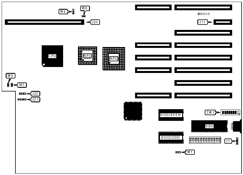
CONNECTIONS | |||
|
Purpose |
Location |
Purpose |
Location |
|
External battery |
J1 |
Speaker |
J22 |
|
32-bit system memory card power |
J11 |
Turbo LED |
W7 |
|
32-bit system memory card |
J20 |
Reset switch |
W9 |
|
Power LED & keylock |
J21 | ||
|
Note:The system memory card is inserted into both J11 & J20. | |||
|
USER CONFIGURABLE SETTINGS | |||
|
Function |
Jumper/Switch |
Position | |
| » |
Factory configured - do not alter |
SW1/1 |
On |
|
NPU enabled |
SW1/2 |
On | |
|
NPU disabled |
SW1/2 |
Off | |
| » |
Factory configured - do not alter |
SW1/3 |
Off |
| » |
Video BIOS shadowing enabled |
SW1/4 |
On |
|
Video BIOS shadowing disabled |
SW1/4 |
Off | |
| » |
Factory configured - do not alter |
SW1/5 |
Off |
| » |
Monitor type select color |
SW1/6 |
On |
|
Monitor type select monochrome |
SW1/6 |
Off | |
|
Cache enabled |
SW1/7 |
On | |
|
Cache disabled |
SW1/7 |
Off | |
| » |
Factory configured - do not alter |
SW1/8 |
Off |
|
BIOS type select 27128 |
W1 |
pins 1 & 2 closed | |
|
BIOS type select 27256 |
W1 |
pins 2 & 3 closed | |
|
NPU mode select synchronous with CPU |
W4 W6 |
pins 2 & 3 closed open | |
|
NPU mode select asynchronous with CPU |
W4 W6 |
pins 1 & 2 closed closed | |
|
Note:Cache configuration applies to main memory boards M100C and M400C only. | |||
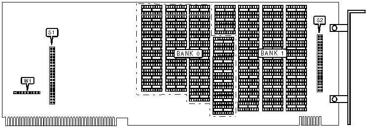
SYSTEM MEMORY CARD MODEL M100
|
CONNECTIONS | |
|
Purpose |
Location |
|
32-bit piggy back memory card |
S1 & S2 |
|
DRAM CONFIGURATION | |||
|
Size |
Bank 0 |
Bank 1 |
Jumper W1 |
|
1MB |
(36) 256K x 1 |
NONE |
pins 2 & 3, 4 & 5, 7 & 8 closed |
|
2MB |
(36) 256K x 1 |
(36) 256K x 1 |
pins 1 & 2, 4 & 5, 7 & 8 closed |
|
CONNECTIONS | |
|
Purpose |
Location |
|
32-bit piggy back memory card |
S1 & S2 |
|
DRAM CONFIGURATION | |||
|
Size |
Bank 0 |
Bank 1 |
Jumper W1 |
|
4MB |
(36) 1M x 1 |
NONE |
pins 1 & 2, 3 & 4 closed |
|
8MB |
(36) 1M x 1 |
(36) 1M x 1 |
pins 3 & 4 closed |
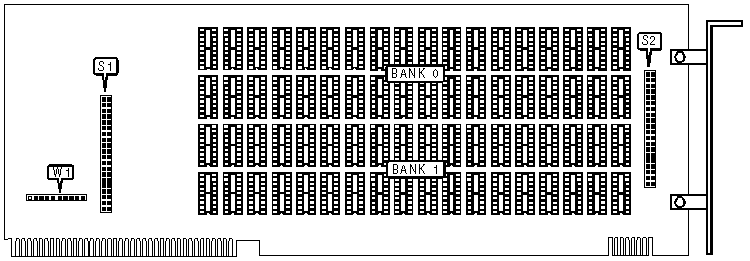
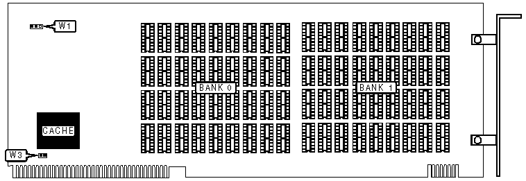
SYSTEM MEMORY CARD MODEL M300
|
CONNECTIONS | |
|
Purpose |
Location |
|
32-bit piggy back memory card |
S1 & S2 |
|
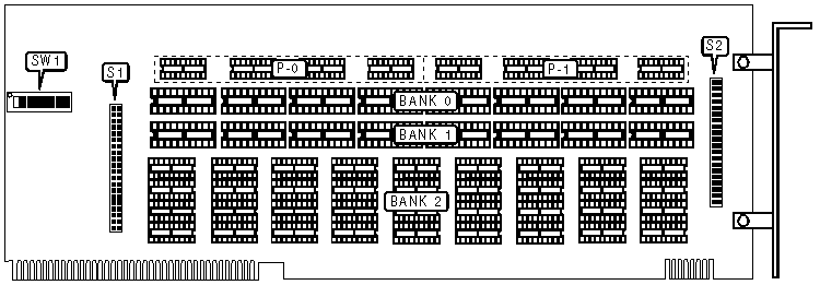
DRAM CONFIGURATION | ||||||
|
Size |
Bank 0 |
Parity (P-0) |
Bank 1 |
Parity (P-1) |
Bank 2 |
SW1 |
|
1MB |
(8) 44256 |
(4) 4464 |
NONE |
NONE |
NONE |
switches 5, 6, & 8 closed |
|
2MB |
(8) 44256 |
(4) 4464 |
(8) 44256 |
(4) 4464 |
NONE |
switches 3, 5, 6, & 8 closed |
|
6MB |
(8) 44256 |
(4) 4464 |
(8) 44256 |
(4) 4464 |
(36) 411000 |
switches 2, 3, 5, 6, & 8 closed |
|
CONNECTIONS | |
|
Purpose |
Location |
|
32-bit piggy back memory card |
S1 & S2 |
|
DRAM CONFIGURATION | ||||
|
Size |
Bank 0 |
Bank 1 |
Jumper W1 |
Jumper W3 |
|
1MB |
(36) 256K x 1 |
NONE |
pins 1 & 2 closed |
closed |
|
2MB |
(36) 256K x 1 |
(36) 256K x 1 |
pins 2 & 3 closed |
closed |
|
Note:Jumper W3 enables cache controller chip. Disabling this jumper will decrease system speed. | ||||
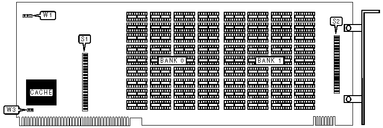
SYSTEM MEMORY CARD MODEL M400C
|
DRAM CONFIGURATION | ||||
|
Size |
Bank 0 |
Bank 1 |
Jumper W1 |
Jumper W3 |
|
4MB |
(36) 1M x 1 |
NONE |
pins 1 & 2 closed |
closed |
|
8MB |
(36) 1M x 1 |
(36) 1M x 1 |
pins 2 & 3 closed |
closed |
|
Note:Jumper W3 enables cache controller chip. Disabling this jumper will decrease system speed. | ||||