INTERLOGIC INDUSTRIES
ASC386SX/486SLC VER.C
|
Processor |
80386SX/CX486SLC |
|
Processor Speed |
33/40MHz |
|
Chip Set |
ALI |
|
Max. Onboard DRAM |
16MB |
|
Cache |
None |
|
BIOS |
AM |
|
Dimensions |
156mm x 121mm |
|
I/O Options |
Floppy drive interface, IDE interface, parallel port, serial ports (2) |
|
NPU Options |
80387SX |
|
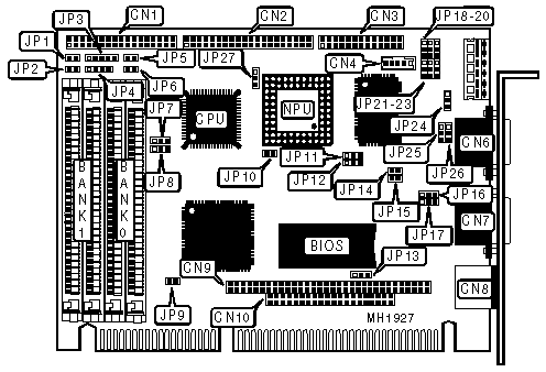
CONNECTIONS | |||
|
Purpose |
Location |
Purpose |
Location |
|
Floppy drive interface |
CN1 |
Video module (PC/104) interface |
CN10 |
|
IDE interface |
CN2 |
Reset switch |
JP1 |
|
Parallel port |
CN3 |
IDE interface LED |
JP2 |
|
Keyboard connector |
CN4 |
Power LED & keylock |
JP3 |
|
Serial port 1 |
CN6 |
Speaker |
JP4 |
|
Serial port 2 |
CN7 |
Turbo switch |
JP5 |
|
Keyboard port |
CN8 |
Turbo LED |
JP6 |
|
Video module (PC/104) interface |
CN9 | ||
|
USER CONFIGURABLE SETTINGS | |||
|
Function |
Jumper |
Position | |
|
» |
Parity enabled |
JP9 |
Open |
|
Parity disabled |
JP9 |
Closed | |
|
» |
Monitor type select monochrome |
JP10 |
Open |
|
Monitor type select color |
JP10 |
Closed | |
|
» |
Parallel port unidirectional (printer) |
JP14 |
Closed |
|
Parallel port bidirectional |
JP14 |
Open | |
|
» |
Watch-dog timer disabled |
JP17 |
Open |
|
Watch-dog timer is reset after time-out period ends |
JP17 |
pins 1 & 2 closed | |
|
Activate NMI to CPU when watch-dog timer time-out period ends |
JP17 |
pins 2 & 3 closed | |
|
» |
IDE interface is not a Special Designed XT |
JP20 |
pins 2 & 3 closed |
|
IDE interface is a Special Designed XT |
JP20 |
pins 1 & 2 closed | |
|
» |
Floppy drive interface enabled |
JP24 |
pins 1 & 2 closed |
|
Floppy drive interface disabled |
JP24 |
pins 2 & 3 closed | |
|
» |
IDE interface enabled |
JP25 |
pins 1 & 2 closed |
|
IDE interface disabled |
JP25 |
pins 2 & 3 closed | |
|
» |
NPU synchronous with CPU |
JP27 |
pins 1 & 2 closed |
|
NPU asynchronous |
JP27 |
pins 2 & 3 closed | |
|
SERIAL PORT CONFIGURATION | |||||
|
Port 1 (CN6) |
Port 2 (CN7) |
JP18 |
JP19 |
JP21 |
JP23 |
|
3F8h - 3FFh |
2F8h - 2FFh |
pins 1 & 2 |
pins 1 & 2 |
pins 1 & 2 |
pins 1 & 2 |
|
3F8h - 3FFh |
Disabled |
pins 1 & 2 |
pins 1 & 2 |
N/A |
pins 2 & 3 |
|
Disabled |
2F8h - 2FFh |
pins 2 & 3 |
N/A |
pins 1 & 2 |
pins 1 & 2 |
|
3E8h - 3EFh |
2E8h - 2EFh |
pins 1 & 2 |
pins 2 & 3 |
pins 2 & 3 |
pins 1 & 2 |
|
3E8h - 3EFh |
Disabled |
pins 1 & 2 |
pins 2 & 3 |
N/A |
pins 2 & 3 |
|
Disabled |
2E8h - 2EFh |
pins 2 & 3 |
N/A |
pins 2 & 3 |
pins 1 & 2 |
|
Disabled |
Disabled |
pins 2 & 3 |
N/A |
N/A |
pins 2 & 3 |
|
Note:pins designated should be in the closed position. | |||||
|
SERIAL PORT INTERRUPT SELECT | |||
|
Port 1 (CN6) |
Port 2 (CN7) |
JP11 |
JP12 |
|
IRQ4 |
IRQ3 |
pins 2 & 3 closed |
pins 1 & 2 closed |
|
IRQ3 |
IRQ4 |
pins 1 & 2 closed |
pins 2 & 3 closed |
|
DRAM CONFIGURATION | ||
|
Size |
Bank 0 |
Bank 1 |
|
512KB |
(2) 256K x 9 |
NONE |
|
1MB |
(2) 256K x 9 |
(2) 256K x 9 |
|
2MB |
(2) 1M x 9 |
NONE |
|
4MB |
(2) 1M x 9 |
(2) 1M x 9 |
|
8MB |
(2) 4M x 9 |
NONE |
|
16MB |
(2) 4M x 9 |
(2) 4M x 9 |
|
WATCHDOG TIMER TIME-OUT CONFIGURATION | ||
|
Time-out period |
JP15 |
JP16 |
|
500ms |
Closed |
pins 1 & 2 closed |
|
1 second |
Open |
pins 1 & 2 closed |
|
2.5 seconds |
Closed |
pins 2 & 3 closed |
|
5 seconds |
Open |
pins 2 & 3 closed |
|
BUS CLOCK SETTING | |||
|
33Mhz CPU |
40Mhz CPU |
JP7 |
JP8 |
|
6.6Mhz bus clock |
8Mhz bus clock |
pins 1 & 2 closed |
pins 1 & 2 closed |
|
8.25Mhz bus clock |
10Mhz bus clock |
pins 2 & 3 closed |
pins 2 & 3 closed |
|
11Mhz bus clock |
13.33Mhz bus clock |
pins 1 & 2 closed |
pins 2 & 3 closed |
|
13.2Mhz bus clock |
16Mhz bus clock |
pins 2 & 3 closed |
pins 1 & 2 closed |
|
PARALLEL PORT CONFIGURATION | ||||
|
Port |
JP13 |
JP22 |
JP26 | |
| » |
378h/IRQ7 |
pins 1 & 2 closed |
pins 1 & 2 closed |
pins 1 & 2 closed |
|
378h/IRQ5 |
pins 2 & 3 closed |
pins 1 & 2 closed |
pins 1 & 2 closed | |
|
278h/IRQ5 |
pins 2 & 3 closed |
pins 1 & 2 closed |
pins 2 & 3 closed | |
|
278h/IRQ7 |
pins 1 & 2 closed |
pins 1 & 2 closed |
pins 2 & 3 closed | |
|
Disabled |
N/A |
pins 2 & 3 closed |
N/A | |