EVEREX SYSTEMS, INC.
AGI 386-20 EV-1830B
|
Processor |
80386DX |
|
Processor Speed |
20MHz |
|
Chip Set |
C & T |
|
Max. Onboard DRAM |
1MB |
|
Cache |
None |
|
BIOS |
AMI |
|
Dimensions |
355mm x 304mm |
|
I/O Options |
32-bit external memory cards (2), parallel port, serial ports (2) |
|
NPU Options |
80387DX |
|
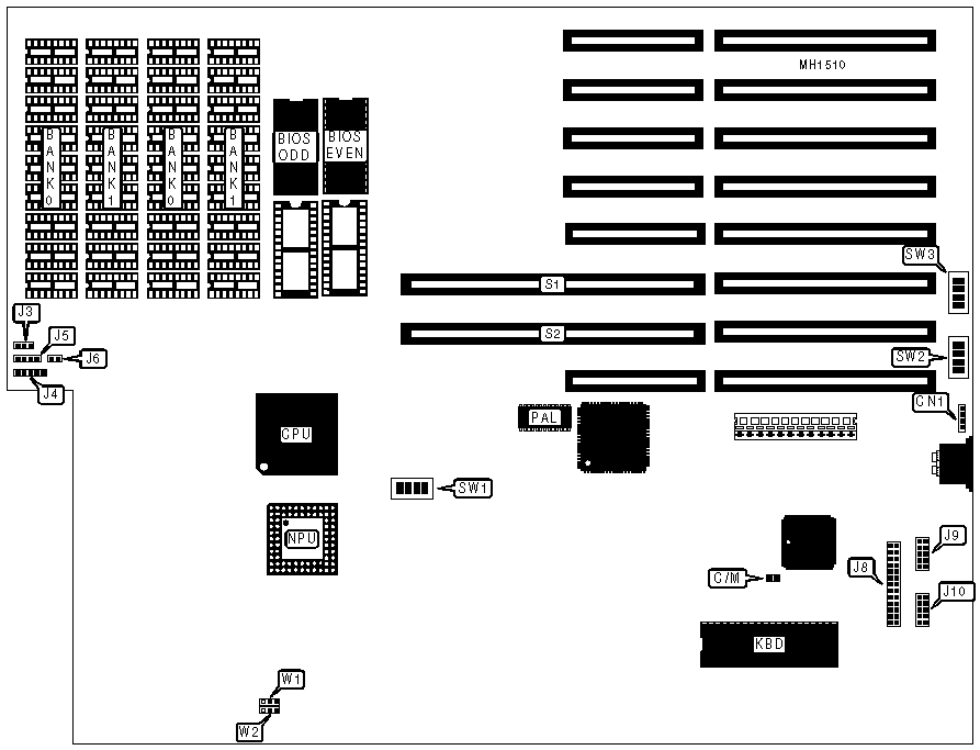
CONNECTIONS | |||
|
Purpose |
Location |
Purpose |
Location |
|
External battery |
CN1 |
Parallel port |
J8 |
|
Turbo LED |
J3 |
Serial port 1 |
J9 |
|
Power LED & keylock |
J4 |
Serial port 2 |
J10 |
|
Speaker |
J5 |
32-bit external memory card |
S1 |
|
Reset switch |
J6 |
32-bit external memory card |
S2 |
|
USER CONFIGURABLE SETTINGS | |||
|
Function |
Jumper |
Position | |
| » |
Monitor select color |
C/M |
Closed |
|
Monitor select monochrome |
C/M |
Open | |
| » |
8-bit cycle bus select 5 wait state |
W1 |
pins 1 & 2 closed |
|
8-bit cycle bus select 4 wait state |
W1 |
pins 2 & 3 closed | |
| » |
16-bit cycle bus select 2 wait state |
W2 |
pins 2 & 3 closed |
|
16-bit cycle bus select 1 wait state |
W2 |
pins 1 & 2 closed | |
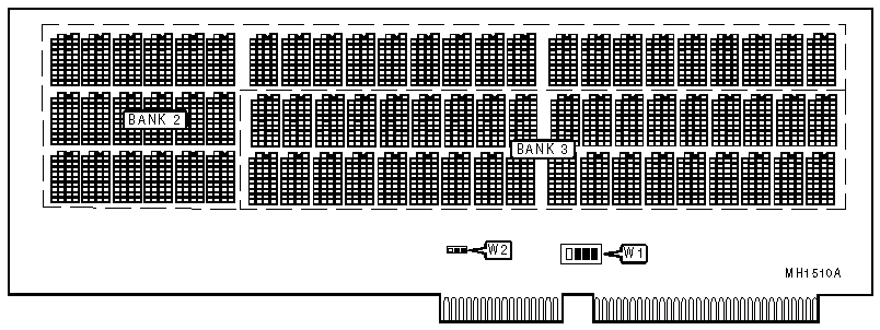
Memory card
|
DRAM CONFIGURATION 1 CARD | |||||
|
System memory |
Total memory |
Bank 0 |
Bank 1 |
Bank 2 |
Bank 3 |
|
1MB |
1MB |
(18) 41256 |
(18) 41256 |
NONE |
NONE |
|
1MB |
2MB |
(18) 41256 |
(18) 41256 |
(36) 41256 |
NONE |
|
1MB |
3MB |
(18) 41256 |
(18) 41256 |
(36) 41256 |
(36) 41256 |
|
1MB |
5MB |
(18) 41256 |
(18) 41256 |
(36) 411000 |
NONE |
|
1MB |
9MB |
(18) 41256 |
(18) 41256 |
(36) 411000 |
(36) 411000 |
|
Note:Banks 2 & 3 are located on the external memory card. | |||||
|
DRAM CONFIGURATION 2 CARDS | ||||
|
External memory |
Card 1/Bank 2 |
Card 1/Bank 3 |
Card 2/Bank 2 |
Card 2/Bank 3 |
|
3MB |
(36) 41256 |
(36) 41256 |
(36) 41256 |
NONE |
|
4MB |
(36) 41256 |
(36) 41256 |
(36) 41256 |
(36) 41256 |
|
6MB |
(36) 41256 |
(36) 41256 |
(36) 411000 |
NONE |
|
10MB |
(36) 41256 |
(36) 41256 |
(36) 411000 |
(36) 411000 |
|
12MB |
(36) 411000 |
(36) 411000 |
(36) 411000 |
NONE |
|
16MB |
(36) 411000 |
(36) 411000 |
(36) 411000 |
(36) 411000 |
|
Note:Total memory includes system memory and external memory. | ||||
|
DRAM JUMPER CONFIGURATION | |||||
|
System memory |
External memory |
SW1/1 |
SW1/2 |
SW1/3 |
SW1/4 |
|
1MB |
0MB |
On |
On |
On |
On |
|
1MB |
4MB |
Off |
On |
On |
On |
|
1MB |
8MB |
Off |
Off |
On |
On |
|
1MB |
14MB |
Off |
Off |
Off |
On |
|
DRAM JUMPER CONFIGURATION 1 CARD | |||||
|
System memory |
External memory |
W1/1 |
W1/2 |
W1/3 |
W1/4 |
|
1MB |
1MB |
On |
On |
On |
On |
|
1MB |
2MB |
On |
On |
On |
Off |
|
1MB |
4MB |
Off |
On |
On |
On |
|
1MB |
8MB |
Off |
On |
On |
Off |
|
Note:Switch W1 is located on the external memory card. | |||||
|
DRAM JUMPER CONFIGURATION 2 CARDS | ||||||
|
System memory |
External memory |
W1/1 |
W1/2 |
W1/3 |
W1/4 |
W2 |
|
1MB |
3MB |
Off |
On |
Off |
Off |
pins 2 & 3 |
|
1MB |
4MB |
Off |
On |
Off |
On |
pins 2 & 3 |
|
1MB |
6MB |
On |
On |
Off |
Off |
pins 2 & 3 |
|
1MB |
10MB |
On |
On |
Off |
On |
pins 1 & 2 |
|
1MB |
12MB |
On |
On |
Off |
Off |
pins 1 & 2 |
|
1MB |
16MB |
Off |
Off |
On |
On |
pins 1 & 2 |
|
Note:Switch W1 and jumper W2 are located on the external memory card. | ||||||
|
SERIAL PORT CONFIGURATION | ||||||
|
Port 1 |
Port 2 |
SW2/1 |
SW2/2 |
SW3/1 |
SW3/2 | |
| » |
COM1 |
COM2 |
Off |
Off |
On |
On |
|
COM1 |
Disabled |
Off |
On |
On |
Off | |
|
Disabled |
COM2 |
On |
Off |
Off |
On | |
|
Disabled |
Disabled |
On |
On |
Off |
Off | |
|
PARALLEL PORT CONFIGURATION | |||||||
|
LPT |
Address |
IRQ |
SW2/3 |
SW2/4 |
SW3/3 |
SW3/4 | |
| » |
2 |
378-37Fh |
7 |
Off |
Off |
Off |
On |
|
3 |
278-27Fh |
5 |
Off |
On |
On |
Off | |
|
Disabled |
N/A |
N/A |
On |
On |
Off |
Off | |