COMPAQ COMPUTER CORPORATION
DESKPRO 286 (VERSION 2)
|
Processor |
80286 |
|
Processor Speed |
8MHz |
|
Chip Set |
ETEQ |
|
Max. Onboard DRAM |
2.125MB |
|
Cache |
None |
|
BIOS |
Compaq |
|
Dimensions |
330mm x 218mm |
|
I/O Options |
None |
|
NPU Options |
80287 |
|
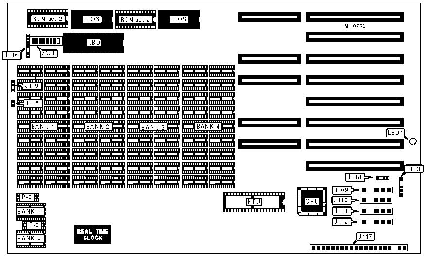
CONNECTIONS | |||
|
Purpose |
Location |
Purpose |
Location |
|
Fixed drive power |
J109 |
Proprietary keyboard connector |
J116 |
|
Fixed drive/Tape backup power |
J110 |
Main power |
J117 |
|
Floppy drive power |
J111 |
External battery |
J118 |
|
Floppy drive power |
J112 |
Keylock |
J119 |
|
Monitor power |
J113 |
Onboard power LED |
LED1 |
|
Speaker |
J115 | ||
|
USER CONFIGURABLE SETTINGS | |||
|
Function |
Switch |
Position | |
| » |
CPU speed select switchable at keyboard |
SW1/6 |
Off |
|
CPU speed select forced slow |
SW1/6 |
On | |
| » |
Factory configured - do not alter |
SW1/7 |
Off |
| » |
Monitor type select color |
SW1/8 |
On |
|
Monitor type select monochrome |
SW1/8 |
Off | |
|
DRAM CONFIGURATION | ||||||
|
Size |
Bank 0 |
P-0 |
Bank 1 |
Bank 2 |
Bank 3 |
Bank 4 |
|
256KB |
(4) 4464 |
(2) 4164 |
(18) 4164 |
NONE |
NONE |
NONE |
|
512KB |
(4) 4464 |
(2) 4164 |
(18) 4164 |
(18) 4164 |
(18) 4164 |
NONE |
|
640KB |
(4) 4464 |
(2) 4164 |
(18) 4164 |
(18) 4164 |
(18) 4164 |
(18) 4164 |
|
640KB |
(4) 4464 |
(2) 4164 |
(18) 41256 |
NONE |
NONE |
NONE |
|
1.125MB |
(4) 4464 |
(2) 4164 |
(18) 41256 |
(18) 41256 |
NONE |
NONE |
|
1.625MB |
(4) 4464 |
(2) 4164 |
(18) 41256 |
(18) 41256 |
(18) 41256 |
NONE |
|
2.125MB |
(4) 4464 |
(2) 4164 |
(18) 41256 |
(18) 41256 |
(18) 41256 |
(18) 41256 |
|
DRAM JUMPER CONFIGURATION | |||||
|
Size |
SW1/1 |
SW1/2 |
SW1/3 |
SW1/4 |
SW1/5 |
|
Disabled |
N/A |
On |
On |
N/A |
N/A |
|
256KB |
On |
On |
Off |
Off |
Off |
|
512KB |
On |
Off |
On |
Off |
Off |
|
640KB |
On |
Off |
Off |
Off |
Off |
|
640KB |
Off |
Off |
Off |
On |
On |
|
1.125MB |
Off |
Off |
Off |
On |
Off |
|
1.625MB |
Off |
Off |
Off |
Off |
On |
|
2.125MB |
Off |
Off |
Off |
Off |
Off |
|
Notes:Closing both SW1/switch 2 and SW1/switch 3, disables banks 0 & 1 and any onboard ROM. Jumper configurations correlate directly to DRAM configurations. | |||||
|
ROM JUMPER CONFIGURATION | ||||
|
ROM type |
Size |
Speed |
BIOS ROM/Jumper block E1 |
ROM set 2/Jumper block E2 |
|
Static |
8K x 8 |
250ns |
pins 1&2, 4&5, and 7&8 closed |
pins 1&2, 4&5, and 7&8 closed |
|
1Static |
16K x 8 |
250ns |
pins 2&3, 4&5, and 7&8 closed |
pins 2&3, 4&5, and 7&8 closed |
|
Static |
32K x 8 |
250ns |
pins 2&3, 5&6, and 7&8 closed |
pins 2&3, 5&6, and 7&8 closed |
|
Dynamic |
8K x 8 |
150ns |
pins 1&2, 4&5, and 8&9 closed |
pins 1&2, 4&5, and 8&9 closed |
|
Dynamic |
16K x 8 |
150ns |
pins 2&3, 4&5, and 8&9 closed |
pins 2&3, 4&5, and 8&9 closed |
|
2Dynamic |
32K x 8 |
150ns |
pins 2&3, 5&6, and 8&9 closed |
pins 2&3, 5&6, and 8&9 closed |
|
Notes:Settings are accomplished by cutting the conductors on the bottom of the board and re-soldering the indicated locations. 1) Default for BIOS ROM 2) Default for ROM set 2 WARNING : Modifying the factory configurations will void the manufacturer's warranty! | ||||