COMPAQ COMPUTER CORPORATION
DESKPRO 286 (VERSION 1)
|
Processor |
80286 |
|
Processor Speed |
8MHz |
|
Chip Set |
ETEQ |
|
Max. Onboard DRAM |
2.125MB (on system memory card) |
|
Cache |
None |
|
BIOS |
Compaq |
|
Dimensions |
330mm x 218mm |
|
I/O Options |
Proprietary system memory card |
|
NPU Options |
80287 |
|
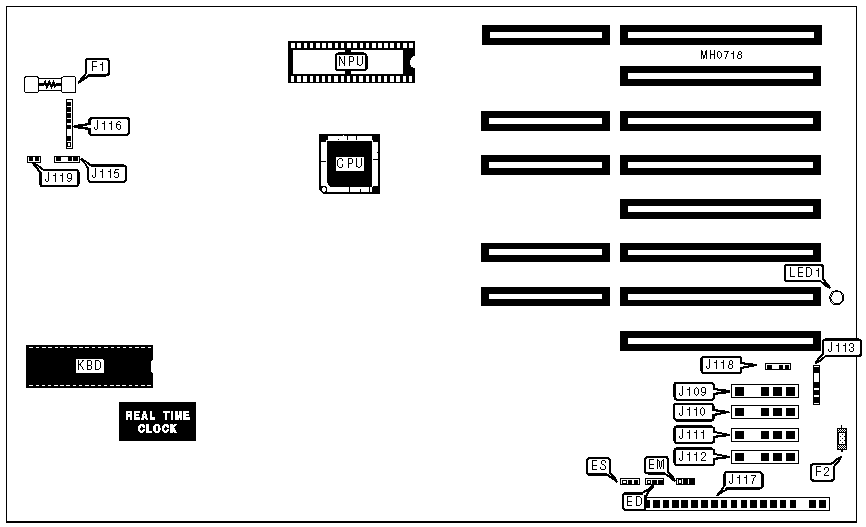
CONNECTIONS |
|||
|
Purpose |
Location |
Purpose |
Location |
|
Keyboard power fuse |
F1 |
Speaker |
J115 |
|
Monitor power fuse |
F2 |
Proprietary keyboard plug |
J116 |
|
Fixed drive power |
J109 |
Main power |
J117 |
|
Fixed drive/tape backup power |
J110 |
External battery |
J118 |
|
Floppy drive power |
J111 |
Keylock |
J119 |
|
Floppy drive power |
J112 |
Onboard power LED |
LED1 |
|
Monitor power |
J113 |
|
|
|
USER CONFIGURABLE SETTINGS |
|||
|
Function |
Jumper |
Position |
|
|
» |
Monitor type select Compaq graphics/color |
ED |
pins 2 & 3 closed |
|
|
Monitor type select monochrome other than Compaq |
ED |
pins 1 & 2 closed |
|
» |
Factory configured - do not alter |
EM |
pins 1 & 2 closed |
|
» |
CPU speed select switchable at keyboard |
ES |
pins 1 & 2 closed |
|
|
CPU speed select forced slow |
ES |
pins 2 & 3 closed |
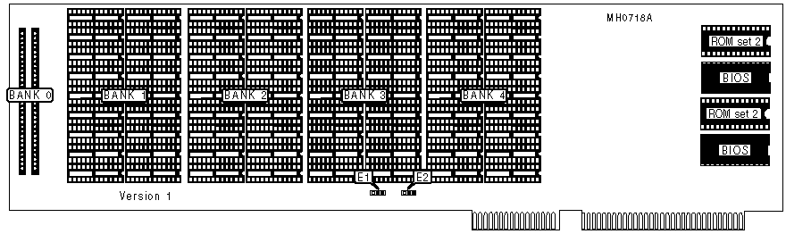
SYSTEM MEMORY CARD (VERSION 1)
|
ROM JUMPER CONFIGURATION |
||||
|
ROM type |
Size |
Speed |
BIOS ROM / Jumper block E |
ROM set 2 / Jumper block E |
|
Static |
8K x 8 |
250ns |
pins 7&8, 10&11, 13&14 closed |
pins 1&2, 4&5, 22&23 closed |
|
1 Static |
16K x 8 |
250ns |
pins 8&9, 10&11, 13&14 closed |
pins 2&3, 4&5, 22&23 closed |
|
Static |
32K x 8 |
250ns |
pins 8&9, 11&12, 13&14 closed |
pins 2&3, 5&6, 22&23 closed |
|
Dynamic |
8K x 8 |
150ns |
pins 7&8, 10&11, 14&15 closed |
pins 1&2, 4&5, 20&21 closed |
|
Dynamic |
16K x 8 |
150ns |
pins 8&9, 10&11, 14&15 closed |
pins 2&3, 4&5, 20&21 closed |
|
2Dynamic |
32K x 8 |
150ns |
pins 8&9, 11&12, 14&15 closed |
pins 2&3, 5&6, 20&21 closed |
|
Note: Settings are accomplished by cutting the conductors on the bottom of the board and re-soldering the indicated locations. 1) Default for BIOS ROM 2) Default for ROM set 2 WARNING: Modifying the factory configurations will void the manufacturers warranty! |
||||
|
DRAM CONFIGURATION |
|||||
|
Size |
Bank 0 |
Bank 1 |
Bank 2 |
Bank 3 |
Bank 4 |
|
256KB |
(2) 64K x 9 |
(18) 4164 |
NONE |
NONE |
NONE |
|
512KB |
(2) 64K x 9 |
(18) 4164 |
(18) 4164 |
(18) 4164 |
NONE |
|
640KB |
(2) 64K x 9 |
(18) 4164 |
(18) 4164 |
(18) 4164 |
(18) 4164 |
|
640KB |
(2) 64K x 9 |
(18) 41256 |
NONE |
NONE |
NONE |
|
1.125MB |
(2) 64K x 9 |
(18) 41256 |
(18) 41256 |
NONE |
NONE |
|
1.625MB |
(2) 64K x 9 |
(18) 41256 |
(18) 41256 |
(18) 41256 |
NONE |
|
2.125MB |
(2) 64K x 9 |
(18) 41256 |
(18) 41256 |
(18) 41256 |
(18) 41256 |
|
Note: Bank 0is permanently affixed to the memory board and is not alterable. |
|||||
|
DRAM JUMPER CONFIGURATION |
||
|
Size |
E1 |
E2 |
|
256KB |
pins 1 & 2 closed |
pins 2 & 3 closed |
|
512KB |
pins 1 & 2 closed |
pins 1 & 2 closed |
|
640KB |
pins 1 & 2 closed |
pins 2 & 3 closed |
|
640KB |
pins 2 & 3 closed |
pins 1 & 2 closed |
|
1.125MB |
pins 2 & 3 closed |
pins 2 & 3 closed |
|
1.625MB |
pins 2 & 3 closed |
pins 2 & 3 closed |
|
2.125MB |
pins 2 & 3 closed |
pins 2 & 3 closed |
SYSTEM MEMORY CARD (VERSIONS 2 & 3)
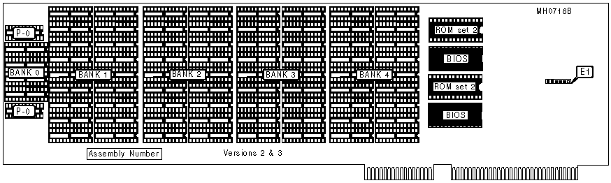
Note: Versions 2 & 3 are differentiated by
Their assembly numbers
Version 2 has assembly #'s 000178-XXX
Version 3 has assembly #'s 000382-XXX
|
DRAM CONFIGURATION |
||||||
|
Size |
Bank 0 |
P-0 |
Bank 1 |
Bank 2 |
Bank 3 |
Bank 4 |
|
256KB |
(4) 4464 |
(2) 4164 |
(18) 4164 |
NONE |
NONE |
NONE |
|
512KB |
(4) 4464 |
(2) 4164 |
(18) 4164 |
(18) 4164 |
(18) 4164 |
NONE |
|
640KB |
(4) 4464 |
(2) 4164 |
(18) 4164 |
(18) 4164 |
(18) 4164 |
(18) 4164 |
|
* 640KB |
(4) 4464 |
(2) 4164 |
(18) 41256 |
NONE |
NONE |
NONE |
|
1.125MB |
(4) 4464 |
(2) 4164 |
(18) 41256 |
(18) 41256 |
NONE |
NONE |
|
1.625MB |
(4) 4464 |
(2) 4164 |
(18) 41256 |
(18) 41256 |
(18) 41256 |
NONE |
|
2.125MB |
(4) 4464 |
(2) 4164 |
(18) 41256 |
(18) 41256 |
(18) 41256 |
(18) 41256 |
|
Notes: Version 3 of the system memory board does not support the second 640KB configuration using (18) 41256 chips in bank 1. Bank 0 is permanently affixed to the memory board and is not alterable. |
||||||
|
DRAM JUMPER CONFIGURATION |
||
|
Size |
Version 2 E1 |
Version 3 E1 |
|
256KB |
pins 1 & 2 and 4 & 5 closed |
pins 2 & 3 and 4 & 5 closed |
|
512KB |
pins 1 & 2 and 4 & 5 closed |
pins 1 & 2 and 4 & 5 closed |
|
640KB |
pins 1 & 2 and 5 & 6 closed |
pins 1 & 2 and 5 & 6 closed |
|
640KB |
pins 2 & 3 and 4 & 5 closed |
N/A |
|
1.125MB |
pins 2 & 3 and 5 & 6 closed |
pins 2 & 3 and 5 & 6 closed |
|
1.625MB |
pins 2 & 3 and 5 & 6 closed |
pins 2 & 3 and 5 & 6 closed |
|
2.125MB |
pins 2 & 3 and 5 & 6 closed |
pins 2 & 3 and 5 & 6 closed |
|
ROM JUMPER CONFIGURATION |
||||
|
ROM type |
Size |
Speed |
BIOS ROM/Jumper Block E2 |
ROM set 2/Jumper Block E3 |
|
Static |
8K x 8 |
250ns |
pins 1&2, 4&5, 7&8 closed |
pins 1&2, 4&5, 7&8 closed |
|
1Static |
16K x 8 |
250ns |
pins 2&3, 4&5, 7&8 closed |
pins 2&3, 4&5, 7&8 closed |
|
Static |
32K x 8 |
250ns |
pins 2&3, 5&6, 7&8 closed |
pins 2&3, 5&6, 7&8 closed |
|
Dynamic |
8K x 8 |
150ns |
pins 1&2, 4&5, 8&9 closed |
pins 1&2, 4&5, 8&9 closed |
|
Dynamic |
16K x 8 |
150ns |
pins 2&3, 4&5, 8&9 closed |
pins 2&3, 4&5, 8&9 closed |
|
2Dynamic |
32K x 8 |
150ns |
pins 2&3, 5&6, 8&9 closed |
pins 2&3, 5&6, 8&9 closed |
|
Notes: Settings are accomplished by cutting the conductors on the bottom of the board and re-soldering the indicated locations. 1) Default for BIOS ROM 2) Default for ROM set 2 WARNING: Modifying the factory configurations will void the manufacturers warranty! |
||||