CLUB AMERICAN TECHNOLOGIES, INC.
FALCON 400 SERIES
|
Processor |
80486SX/80486DX |
|
Processor Speed |
20/25/33MHz |
|
Chip Set |
VLSI |
|
Max. Onboard DRAM |
64MB |
|
Cache |
64/256KB |
|
BIOS |
AMI |
|
Dimensions |
330mm x 218mm |
|
I/O Options |
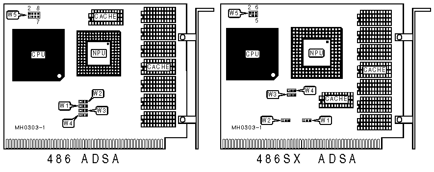
32-bit external CPU/NPU card slot |
|
NPU Options |
80487SX/4167 (on external CPU/NPU card) |
|
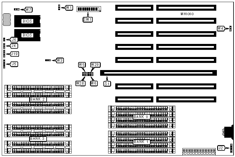
CONNECTIONS |
|||
|
Purpose |
Location |
Purpose |
Location |
|
External battery |
J2 |
Reset switch |
J6 |
|
Turbo LED |
J4 |
Speaker |
J19 |
|
Power LED & keylock |
J5 |
CPU/NPU expansion card |
S1 |
|
USER CONFIGURABLE SETTINGS |
|||
|
Function |
Jumper/Switch |
Position |
|
|
» |
Factory configured - do not alter |
W1 |
pins 1 & 2 closed |
|
» |
CPU speed select switchable from keyboard |
W3 |
pins 1 & 2 closed |
|
|
CPU speed select forced high |
W3 |
Open |
|
|
CPU speed select forced low |
W3 |
pins 2 & 3 closed |
|
» |
Monitor type select color |
W4 |
pins 2 & 3 closed |
|
|
Monitor type select monochrome |
W4 |
pins 1 & 2 closed |
|
» |
Factory configured - do not alter |
W7 |
pins 1 & 2 closed |
|
» |
Factory configured - do not alter |
SW1/1 |
On |
|
» |
Factory configured - do not alter |
SW1/2 |
Off |
|
» |
Factory configured - do not alter |
SW1/3 |
On |
|
» |
Shadow video BIOS enabled |
SW1/4 |
On |
|
|
Shadow video BIOS disabled |
SW1/4 |
Off |
|
» |
Factory configured - do not alter |
SW1/5 |
On |
|
» |
Shadow system BIOS enabled |
SW1/6 |
On |
|
|
Shadow system BIOS disabled |
SW1/6 |
Off |
|
DRAM CONFIGURATION |
||||
|
Size |
Bank 0 |
Bank 1 |
Bank 2 |
Bank 3 |
|
1MB |
(4) 256K x 9 |
NONE |
NONE |
NONE |
|
2MB |
(4) 256K x 9 |
(4) 256K x 9 |
NONE |
NONE |
|
4MB |
(4) 1M x 9 |
NONE |
NONE |
NONE |
|
6MB |
(4) 256K x 9 |
(4) 256K x 9 |
(4) 1M x 9 |
NONE |
|
8MB |
(4) 1M x 9 |
(4) 1M x 9 |
NONE |
NONE |
|
10MB |
(4) 256K x 9 |
(4) 256K x 9 |
(4) 1M x 9 |
(4) 1M x 9 |
|
12MB |
(4) 1M x 9 |
(4) 1M x 9 |
(4) 1M x 9 |
NONE |
|
16MB |
(4) 1M x 9 |
(4) 1M x 9 |
(4) 1M x 9 |
(4) 1M x 9 |
|
16MB |
(4) 4M x 9 |
NONE |
NONE |
NONE |
|
24MB |
(4) 1M x 9 |
(4) 1M x 9 |
(4) 4M x 9 |
NONE |
|
32MB |
(4) 4M x 9 |
(4) 4M x 9 |
NONE |
NONE |
|
40MB |
(4) 4M x 9 |
(4) 4M x 9 |
(4) 1M x 9 |
(4) 1M x 9 |
|
48MB |
(4) 4M x 9 |
(4) 4M x 9 |
(4) 4M x 9 |
NONE |
|
64MB |
(4) 4M x 9 |
(4) 4M x 9 |
(4) 4M x 9 |
(4) 4M x 9 |
|
DRAM JUMPER CONFIGURATION |
||||
|
Size |
W5 |
W6 |
W28 |
W29 |
|
1MB |
pins 2 & 3 closed |
pins 2 & 3 closed |
pins 1 & 2 closed |
pins 2 & 3 closed |
|
2MB |
pins 2 & 3 closed |
pins 2 & 3 closed |
pins 1 & 2 closed |
pins 2 & 3 closed |
|
4MB |
pins 1 & 2 closed |
pins 2 & 3 closed |
pins 1 & 2 closed |
pins 2 & 3 closed |
|
6MB |
pins 2 & 3 closed |
pins 2 & 3 closed |
pins 1 & 2 closed |
pins 2 & 3 closed |
|
8MB |
pins 1 & 2 closed |
pins 2 & 3 closed |
pins 1 & 2 closed |
pins 2 & 3 closed |
|
10MB |
pins 2 & 3 closed |
pins 2 & 3 closed |
pins 1 & 2 closed |
pins 2 & 3 closed |
|
12MB |
pins 1 & 2 closed |
pins 2 & 3 closed |
pins 1 & 2 closed |
pins 2 & 3 closed |
|
16MB |
pins 1 & 2 closed |
pins 2 & 3 closed |
pins 1 & 2 closed |
pins 2 & 3 closed |
|
16MB |
pins 1 & 2 closed |
pins 1 & 2 closed |
pins 1 & 2 closed |
pins 1 & 2 closed |
|
24MB |
pins 1 & 2 closed |
pins 2 & 3 closed |
pins 1 & 2 closed |
pins 1 & 2 closed |
|
32MB |
pins 1 & 2 closed |
pins 1 & 2 closed |
pins 1 & 2 closed |
pins 1 & 2 closed |
|
40MB |
pins 1 & 2 closed |
pins 2 & 3 closed |
pins 1 & 2 closed |
pins 1 & 2 closed |
|
48MB |
pins 1 & 2 closed |
pins 1 & 2 closed |
pins 1 & 2 closed |
pins 1 & 2 closed |
|
64MB |
pins 1 & 2 closed |
pins 1 & 2 closed |
pins 1 & 2 closed |
pins 1 & 2 closed |
|
DRAM SWITCH CONFIGURATION |
||||
|
Size |
SW1/7 |
SW1/8 |
SW1/9 |
SW1/10 |
|
1MB |
On |
On |
On |
On |
|
2MB |
On |
Off |
On |
On |
|
4MB |
On |
On |
On |
Off |
|
6MB |
Off |
On |
On |
On |
|
8MB |
On |
Off |
On |
Off |
|
10MB |
Off |
Off |
On |
On |
|
12MB |
Off |
On |
On |
Off |
|
16MB |
Off |
Off |
On |
Off |
|
16MB |
On |
On |
Off |
Off |
|
24MB |
Off |
On |
Off |
On |
|
32MB |
On |
Off |
Off |
Off |
|
40MB |
Off |
Off |
Off |
On |
|
48MB |
Off |
On |
Off |
Off |
|
64MB |
Off |
Off |
Off |
Off |
|
CACHE CONFIGURATION |
|
|
Size |
Bank 0 |
|
64KB |
(8) 16K x 4 |
|
256KB |
(8) 64K x 4 |
|
CACHE CONFIGURATION |
|||
|
Size |
W1 |
W2 |
W5 |
|
64KB |
pins 2 & 3 closed |
pins 2 & 3 closed |
pins 3 & 4, 5 & 6 open |
|
256KB |
pins 1 & 2 closed |
pins 1 & 2 closed |
pins 3 & 4 closed, 5 & 6 closed |
|
BURST MODE CONFIGURATION |
|||
|
Burst mode |
W3 |
W4 |
W5 |
|
Enabled |
pins 2 & 3 closed |
pins 2 & 3 closed |
pins 1 & 2 closed |
|
Disabled |
pins 1 & 2 closed |
pins 1 & 2 closed |
pins 1 & 2 open |