AST RESEARCH, INC.
PREMIUM/286
MODELS 202143-003, -004 & -006
|
Processor |
80286 |
|
Processor Speed |
10MHz |
|
Chip Set |
AST |
|
Max. Onboard DRAM |
None (2/4 or 8/16MB on external memory card(s)) |
|
Cache |
None |
|
BIOS |
AST |
|
Dimensions |
330mm x 218mm |
|
I/O Options |
32-bit external memory/CPU card slot (2) Floppy drive interface Parallel port Serial port |
|
NPU Options |
80287 |
|
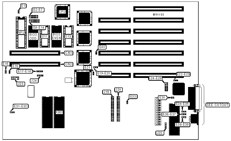
CONNECTIONS | |||
|
Purpose |
Location |
Purpose |
Location |
|
32-bit external memory/CPU card |
CN1 |
Front panel switches & LEDs |
J23 |
|
32-bit external memory/CPU card |
CN2 |
Speaker |
J24 |
|
Floppy drive interface (A: and B:) |
J19 |
Optional ROM (odd) |
U11 |
|
Third floppy drive interface |
J20 |
Optional ROM (even) |
U13 |
|
External battery |
J22 | ||
|
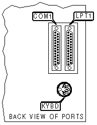
CONNECTIONS | |||
|
Purpose |
Location |
Purpose |
Location |
|
Serial port 1 |
COM1 |
Keyboard |
KYBD |
|
Parallel port |
LPT1 | ||
|
SERIAL PORT CONFIGURATION | |||
|
Serial Port (COM1) |
Jumper E22-E23 |
Jumper E28 |
Jumper E29 |
|
COM1: using IRQ4 |
pins 1 & 2 closed |
closed |
open |
|
COM2: using IRQ3 |
pins 2 & 3 closed |
open |
closed |
|
PARALLEL PORT CONFIGURATION | ||||
|
Parallel Port (LPT) |
Jumper E24 |
Jumper E25 |
Jumper E26 |
Jumper E27 |
|
LPT1: using IRQ7 |
closed |
open |
closed |
open |
|
LPT2: using IRQ7 |
open |
closed |
open |
closed |
|
BIOS TYPE CONFIGURATION | |||
|
BIOS Type |
Jumper E3 |
Jumper E4 |
Jumper E5 |
|
27128 |
open |
open |
closed |
|
27256 |
closed |
closed |
open |
|
OPTIONAL ROM TYPE CONFIGURATION | |||||
|
ROM Type |
Address |
Jumper E9 |
Jumper E10 |
Jumper E11 |
Jumper E12 |
|
27128 |
F000-F7FFh |
open |
open |
closed |
open |
|
27128 |
E800-EFFFh |
open |
open |
open |
closed |
|
27256 |
E000-EFFFh |
closed |
closed |
open |
open |
|
USER CONFIGURABLE SETTINGS | |||
|
Function |
Jumper |
Position | |
|
NPU speed select 8MHz |
E1 & E16 E15 |
open closed | |
|
NPU speed select 5MHz |
E1 & E16 E15 |
closed open | |
| » |
BIOS wait state select one |
E2 |
open |
|
BIOS wait states select zero |
E2 |
closed | |
| » |
Latched PROM BIOS disabled |
E6 |
open |
|
Latched PROM BIOS enabled |
E6 |
closed | |
| » |
Latched PROM BIOS (for optional ROMs) disabled |
E7 and E14 |
E7 open, E14 closed |
|
Latched PROM BIOS (for optional ROMs) enabled |
E7 and E14 |
E7 closed, E14 closed | |
| » |
Optional ROM wait state select one |
E8 |
open |
|
Optional ROM wait states select zero |
E8 |
closed | |
| » |
Factory configured - do not alter |
E13 |
open |
| » |
I/O bus wait states select two (at 10MHz operation) |
E17 |
closed |
|
I/O bus wait state select one (at 10MHz operation) |
E17 |
open | |
| » |
Factory configured - do not alter |
E18 |
open |
| » |
Factory configured - do not alter |
E19-E20 |
closed |
| » |
Factory configured - do not alter |
E21 |
closed |
| » |
Factory configured - do not alter |
E31-E32 |
pins 1 & 2 closed |
| » |
Floppy drive interface enabled |
E33 |
open |
|
Floppy drive interface disabled |
E33 |
closed | |
| » |
Early Address Latch Enabled (#EALE) signal |
E40 |
closed |
|
Buffered Address Latch Enable (#BALE) signal |
E40 |
open | |
|
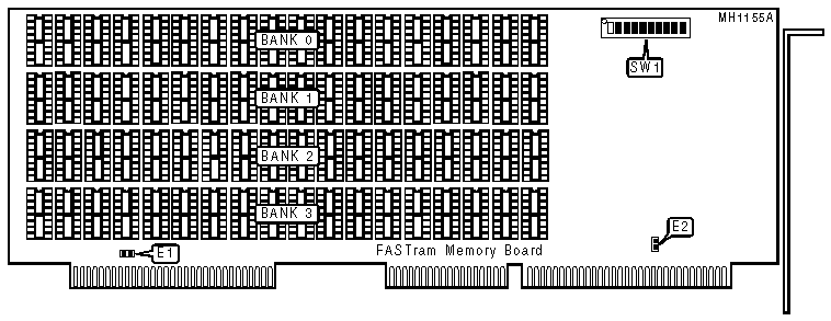
USER CONFIGURABLE SETTINGS FOR FASTRAM MEMORY BOARD | |||
|
Function |
Jumper/Switch |
Position | |
| » |
Parity check enabled |
E1 |
closed |
|
Parity check disabled |
E1 |
open | |
| » |
Wait states select zero |
E2 |
closed |
|
Wait state select one |
E2 |
open | |
| » |
Page mode disabled |
SW1/switch 5 |
closed |
|
Page mode enabled |
SW1/switch 5 |
open | |
| » |
Board installed select first FASTram board installed |
SW1/switch 6 |
closed |
|
Board installed select second FASTram board installed |
SW1/switch 6 |
open | |
|
DRAM CONFIGURATION FOR FASTRAM MEMORY BOARD | ||||
|
Size |
Bank 0 |
Bank 1 |
Bank 2 |
Bank 3 |
|
512KB |
(18) 41256 |
NONE |
NONE |
NONE |
|
1MB |
(18) 41256 |
(18) 41256 |
NONE |
NONE |
|
1.5MB |
(18) 41256 |
(18) 41256 |
(18) 41256 |
NONE |
|
2MB |
(18) 41256 |
(18) 41256 |
(18) 41256 |
(18) 41256 |
|
DRAM SWITCH CONFIGURATION FOR FASTRAM MEMORY BOARD | ||||
|
Recognized by System |
SW1/switch 1 |
SW1/switch 2 |
SW1/switch 3 |
SW1/switch 4 |
|
128KB |
closed |
closed |
closed |
closed |
|
256KB |
open |
closed |
closed |
closed |
|
384KB |
closed |
open |
closed |
closed |
|
512KB |
open |
open |
closed |
closed |
|
640KB |
closed |
closed |
open |
closed |
|
768KB |
open |
closed |
open |
closed |
|
896KB |
closed |
open |
open |
closed |
|
1024KB |
open |
open |
open |
closed |
|
1152KB |
closed |
closed |
closed |
open |
|
1280KB |
open |
closed |
closed |
open |
|
1408KB |
closed |
open |
closed |
open |
|
1536KB |
open |
open |
closed |
open |
|
1664KB |
closed |
closed |
open |
open |
|
1792KB |
open |
closed |
open |
open |
|
1920KB |
closed |
open |
open |
open |
|
2048KB |
open |
open |
open |
open |
|
BASE I/O ADDRESS CONFIGURATION FOR FASTRAM MEMORY BOARD | ||||
|
Base I/O Address |
SW1/switch 7 |
SW1/switch 8 |
SW1/switch 9 |
SW1/switch 10 |
|
0208h |
closed |
closed |
closed |
closed |
|
0218h 1 |
open |
closed |
closed |
closed |
|
0258h 2 |
open |
closed |
open |
closed |
|
0268h |
closed |
open |
open |
closed |
|
02A8h |
closed |
open |
closed |
open |
|
02B8h |
open |
open |
closed |
open |
|
02E8h |
closed |
open |
open |
open |
|
Note 1 :This setting is recommended when this is the first FASTram Memory Board installed.Note 2 :This setting is recommended when this is the second FASTram Memory Board installed. | ||||
|
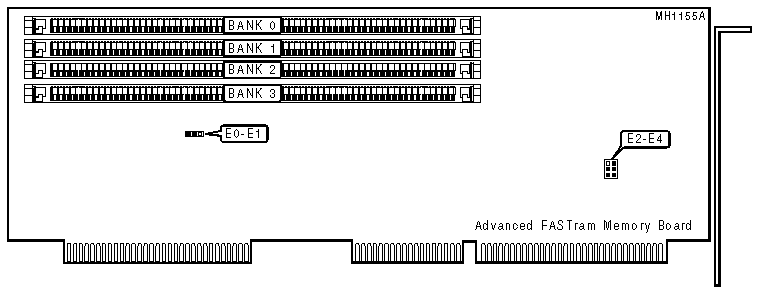
USER CONFIGURABLE SETTINGS FOR ADVANCED FASTRAM MEMORY BOARD | |||
|
Function |
Jumper |
Position | |
| » |
Factory configured - do not alter |
E0-E1 |
pins 2 & 3 closed |
| » |
Board installed select first FASTram board installed |
E2 E4 |
open closed |
|
Board installed select second FASTram board installed |
E2 E4 |
closed open | |
| » |
Memory installed select as expanded |
E3 |
closed |
|
Memory installed select as paged |
E3 |
open | |
|
Note:Parity, wait states, size, and base I/O address are set using the software configuration utility. | |||
|
DRAM CONFIGURATION FOR ADVANCED FASTRAM MEMORY BOARD | ||||
|
Size |
Bank 0 |
Bank 1 |
Bank 2 |
Bank 3 |
|
512KB |
(2) 256K x 9 |
NONE |
NONE |
NONE |
|
1MB |
(2) 256K x 9 |
(2) 256K x 9 |
NONE |
NONE |
|
1.5MB |
(2) 256K x 9 |
(2) 256K x 9 |
(2) 256K x 9 |
NONE |
|
2MB |
(2) 256K x 9 |
(2) 256K x 9 |
(2) 256K x 9 |
(2) 256K x 9 |
|
2MB |
(2) 1M x 9 |
NONE |
NONE |
NONE |
|
3MB |
(2) 256K x 9 |
(2) 256K x 9 |
(2) 1M x 9 |
NONE |
|
4MB |
(2) 1M x 9 |
(2) 1M x 9 |
NONE |
NONE |
|
5MB |
(2) 256K x 9 |
(2) 256K x 9 |
(2) 1M x 9 |
(2) 1M x 9 |
|
6MB |
(2) 1M x 9 |
(2) 1M x 9 |
(2) 1M x 9 |
NONE |
|
8MB |
(2) 1M x 9 |
(2) 1M x 9 |
(2) 1M x 9 |
(2) 1M x 9 |