ADVANCED COMPUTER TECHNOLOGY, LTD.
C386
|
Processor |
80386DX |
|
Processor Speed |
25/33/40MHz |
|
Chip Set |
ACT |
|
Max. Onboard DRAM |
16MB |
|
Cache |
32/64/128KB |
|
BIOS |
AMI |
|
Dimensions |
330mm x 218mm |
|
I/O Options |
None |
|
NPU Options |
80387/3167 |
|
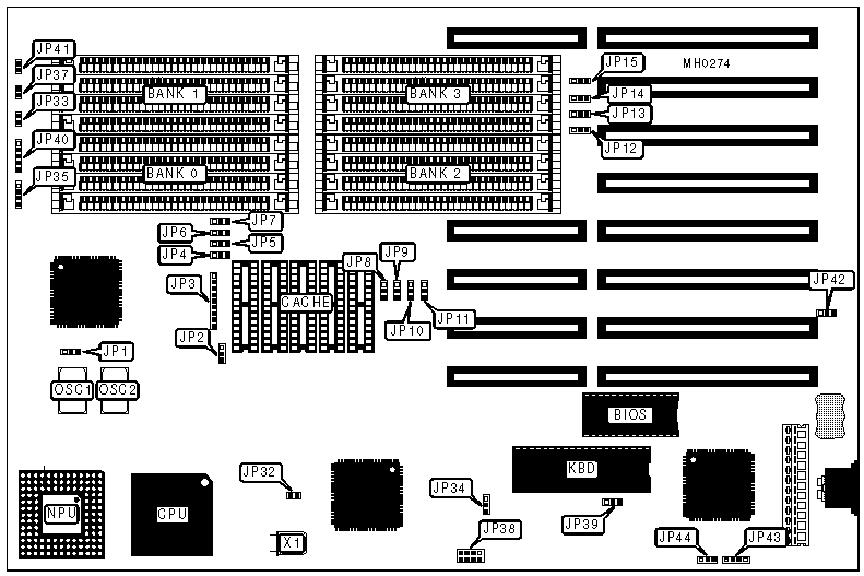
CONNECTIONS | |||
|
Purpose |
Location |
Purpose |
Location |
|
Turbo switch |
JP33 |
Power LED & Keylock |
JP40 |
|
Speaker |
JP35 |
Reset switch |
JP41 |
|
Turbo LED |
JP37 |
External battery |
JP43 |
|
USER CONFIGURABLE SETTINGS | |||
|
Function |
Jumper |
Position | |
| » |
CPU speed select 33MHz |
JP1 |
pins 1 & 2 closed |
|
CPU speed select 25MHz or 40MHz |
JP1 |
pins 2 & 3 closed | |
| » |
Cache enabled |
JP4 |
pins 1 & 2 closed |
|
Cache disabled |
JP4 |
pins 2 & 3 closed | |
| » |
I/O channel RAM cacheable |
JP5 |
pins 1 & 2 closed |
|
I/O channel RAM non-cacheable |
JP5 |
pins 2 & 3 closed | |
| » |
System BIOS cacheable |
JP6 |
pins 1 & 2 closed |
|
System BIOS non-cacheable |
JP6 |
pins 2 & 3 closed | |
| » |
Video BIOS cacheable |
JP7 |
pins 1 & 2 closed |
|
Video BIOS non-cacheable |
JP7 |
pins 2 & 3 closed | |
| » |
DRAM speed select fast (70 - 120ns) |
JP15 |
pins 1 & 2 closed |
|
DRAM speed select slow (100 - 150ns) |
JP15 |
pins 2 & 3 closed | |
| » |
Parity check enabled |
JP32 |
Closed |
|
Parity check disabled |
JP32 |
Open | |
| » |
Bus speed select 8MHz |
JP34 |
pins 1 & 2 closed |
|
Bus speed select 11MHz |
JP34 |
pins 2 & 3 closed | |
| » |
Keyboard controller turbo pin select 30 |
JP38 |
pins 3 & 4 closed |
|
Keyboard controller turbo pin select 24 |
JP38 |
pins 5 & 6 closed | |
|
Keyboard controller turbo pin select 23 |
JP38 |
pins 7 & 8 closed | |
|
Keyboard controller turbo pin select none |
JP38 |
pins 1 & 2 closed | |
| » |
Monitor type select color |
JP39 |
pins 1 & 2 closed |
|
Monitor type select monochrome |
JP39 |
pins 2 & 3 closed | |
| » |
Power good signal detect from power supply |
JP42 |
pins 1 & 2 closed |
|
Power good signal detect from board |
JP42 |
pins 2 & 3 closed | |
| » |
Battery select internal |
JP44 |
pins 1 & 2 closed |
|
Battery select external |
JP44 |
pins 2 & 3 closed | |
|
CACHE CONFIGURATION | |
|
Size |
Bank 0 |
|
32KB |
(5) 8K x 8 |
|
128KB |
(5) 32K x 8 |
|
CACHE JUMPER CONFIGURATION | ||
|
Size |
JP2 |
JP3 |
|
32KB |
pins 2 & 3 closed |
pins 2 & 3, 4 & 5, 6 & 7, 8 & 9 closed |
|
128KB |
pins 1 & 2 closed |
pins 1 & 2, 3 & 4, 5 & 6, 7 & 8 closed |
|
DRAM CONFIGURATION | ||||
|
Size |
Bank 0 |
Bank 1 |
Bank 2 |
Bank 3 |
|
1MB |
(4) 256K x 9 |
NONE |
NONE |
NONE |
|
2MB |
(4) 256K x 9 |
(4) 256K x 9 |
NONE |
NONE |
|
4MB |
(4) 1M x 9 |
NONE |
NONE |
NONE |
|
6MB |
(4) 256K x 9 |
(4) 256K x 9 |
(4) 1M x 9 |
NONE |
|
8MB |
(4) 1M x 9 |
(4) 1M x 9 |
NONE |
NONE |
|
10MB |
(4) 256K x 9 |
(4) 256K x 9 |
(4) 1M x 9 |
(4) 1M x 9 |
|
12MB |
(4) 1M x 9 |
(4) 1M x 9 |
(4) 1M x 9 |
NONE |
|
16MB |
(4) 1M x 9 |
(4) 1M x 9 |
(4) 1M x 9 |
(4) 1M x 9 |
|
DRAM JUMPER CONFIGURATION | |||||||
|
Size |
JP8 |
JP9 |
JP10 |
JP11 |
JP12 |
JP13 |
JP14 |
|
1MB |
1 & 2 |
2 & 3 |
2 & 3 |
2 & 3 |
1 & 2 |
1 & 2 |
1 & 2 |
|
2MB |
1 & 2 |
1 & 2 |
2 & 3 |
2 & 3 |
2 & 3 |
1 & 2 |
1 & 2 |
|
4MB |
1 & 2 |
2 & 3 |
2 & 3 |
1 & 2 |
1 & 2 |
1 & 2 |
2 & 3 |
|
6MB |
2 & 3 |
1 & 2 |
2 & 3 |
1 & 2 |
1 & 2 |
2 & 3 |
1 & 2 |
|
8MB |
1 & 2 |
1 & 2 |
2 & 3 |
1 & 2 |
2 & 3 |
1 & 2 |
2 & 3 |
|
10MB |
2 & 3 |
2 & 3 |
1 & 2 |
1 & 2 |
2 & 3 |
2 & 3 |
1 & 2 |
|
12MB |
1 & 2 |
2 & 3 |
1 & 2 |
1 & 2 |
1 & 2 |
2 & 3 |
2 & 3 |
|
16MB |
1 & 2 |
1 & 2 |
1 & 2 |
1 & 2 |
2 & 3 |
2 & 3 |
2 & 3 |
|
Note: Pins designated should be in the closed position. | |||||||