EMULEX CORPORATION
DCP386I
|
Card Type |
Serial |
|
Processor |
80386 |
|
Processor Speed |
Unidentified |
|
Chipset |
Unidentified |
|
Maximum Onboard Memory |
1MB DRAM |
|
I/O Options |
Serial ports (8) |
|
Data Bus |
16-bit ISA |
|
Card Size |
Full height, three-quarters length |
|
CONNECTIONS | |||
|
Function |
Label |
Function |
Label |
|
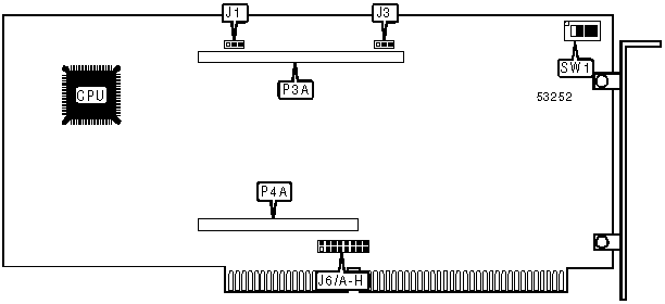
Header to daughterboard P3B or P3C |
P3A |
Header to daughterboard P4B or P3C |
P4A |
|
USER CONFIGURABLE SETTINGS | |||
|
Setting |
Label |
Position | |
| » |
Parity error in board DRAM sends interrupt signal to computer processor |
J1 |
Pins 2 & 3 closed |
|
Parity error in board DRAM sends interrupt signal to board processor |
J1 |
Pins 1 & 2 closed | |
| » |
Shared RAM window size may be 16KB, 32KB, 64KB, or 1MB |
J3 |
Pins 1 & 2 closed |
|
Shared RAM window size may be 16KB, 64KB, or 128KB |
J3 |
Pins 2 & 3 closed | |
|
BASE I/O ADDRESS SELECTION | |||||
|
Setting |
SW1/1 |
SW1/2 |
SW1/3 |
SW1/4 | |
|
13Ch |
On |
On |
Off |
On | |
|
17Ch |
Off |
On |
Off |
On | |
|
1BCh |
On |
Off |
Off |
On | |
|
1FCh |
Off |
Off |
Off |
On | |
|
23Ch |
On |
On |
On |
Off | |
|
27Ch |
Off |
On |
On |
Off | |
|
2BCh |
On |
Off |
On |
Off | |
|
2FCh |
Off |
Off |
On |
Off | |
| » |
33Ch |
On |
On |
Off |
Off |
|
37Ch |
Off |
On |
Off |
Off | |
|
3BCh |
On |
Off |
Off |
Off | |
|
3FCh |
Off |
Off |
Off |
Off | |
|
INTERRUPT SELECTION | ||||||||
|
Setting |
J6/A |
J6/B |
J6/C |
J6/D |
J6/E |
J6/F |
J6/G |
J6/H |
|
2/9 |
Open |
Open |
Open |
Open |
Open |
Open |
Open |
Closed |
|
3 |
Open |
Open |
Open |
Open |
Open |
Open |
Closed |
Open |
|
4 |
Open |
Open |
Open |
Open |
Open |
Closed |
Open |
Open |
|
5 |
Open |
Open |
Open |
Open |
Closed |
Open |
Open |
Open |
|
10 |
Open |
Open |
Open |
Closed |
Open |
Open |
Open |
Open |
|
11 |
Open |
Open |
Closed |
Open |
Open |
Open |
Open |
Open |
|
12 |
Open |
Closed |
Open |
Open |
Open |
Open |
Open |
Open |
|
15 |
Closed |
Open |
Open |
Open |
Open |
Open |
Open |
Open |
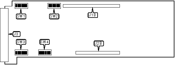
DCP386I (RS-232 DAUGHTERBOARD)
|
CONNECTIONS | |||
|
Function |
Label |
Function |
Label |
|
Header to main board P3A |
P3B |
RS-232 serial ports via unidentified connector |
J3 |
|
Header to main board P4A |
P4B | ||
|
SERIAL PORT CONFIGURATION | |||
|
Setting |
SW1/1 |
SW1/2 |
SW1/3 |
|
DTE |
On |
Off |
Off |
|
DCE |
Off |
On |
On |
|
Note:The settings for SW2/1-SW2/3 through SW4/1-SW4/3 are identical to those for SW1/1-SW1/3. Switches SW1/1-SW1/3 set the configuration for serial port 1, while SW2/1-SW2/3 sets the configuration for serial port 3, SW3/1-SW3/3 sets the configuration for serial port 5, and SW4/1-SW4/3 sets the configuration for serial port 7. | |||
|
SERIAL PORT 2 CONFIGURATION | |||
|
Setting |
SW1/4 |
SW1/5 |
SW1/6 |
|
DTE |
On |
Off |
Off |
|
DCE |
Off |
On |
On |
|
Note:The settings for SW2/4-SW2/6 through SW4/4-SW4/6 are identical to those for SW1/4-SW1/6. Switches SW1/4-SW1/6 set the configuration for serial port 2, while SW2/4-SW2/6 sets the configuration for serial port 4, SW3/4-SW3/6 sets the configuration for serial port 6 and SW4/4-SW4/6 sets the configuration for serial port 8. | |||
|
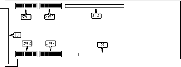
CONNECTIONS | |||
|
Function |
Label |
Function |
Label |
|
Header to main board P3A |
P3C |
RS-422 or X.21 serial ports via unidentified connector |
J3 |
|
Header to main board P4A |
P4C | ||
|
SERIAL PORT CONFIGURATION (ODD) | |||||
|
Setting |
SW1/1 |
SW1/2 |
SW1/3 |
SW1/4 |
SW1/5 |
|
DTE |
On |
Off |
Off |
Off |
Off |
|
DCE |
Off |
On |
On |
On |
On |
|
Note:The settings for SW2/1-SW2/5 through SW4/1-SW4/5 are identical to those for SW1/1-SW1/5. Switches SW1/1-SW1/5 set the configuration for serial port 1, while SW2/1-SW2/5 sets the configuration for serial port 3, SW3/1-SW3/5 sets the configuration for serial port 5, and SW4/1-SW4/5 sets the configuration for serial port 7. | |||||
|
SERIAL PORT CONFIGURATION (EVEN) | |||||
|
Setting |
SW1/6 |
SW1/7 |
SW1/8 |
SW1/9 |
SW1/10 |
|
DTE |
On |
Off |
Off |
Off |
Off |
|
DCE |
Off |
On |
On |
On |
On |
|
Note:The settings for SW2/6-SW2/10 through SW4/6-SW4/10 are identical to those for SW6/10-SW1/10. Switches SW1/6-SW1/10 sets the configuration for serial port 2, while SW2/6-SW2/10 sets the configuration for serial port 4, SW3/6-SW3/10 sets the configuration for serial port 6 and SW4/6-SW4/10 sets the configuration for serial port 8. | |||||
|
MISCELLANEOUS TECHNICAL NOTES |
|
The method for selecting the serial port type (RS-422 or X.21) is unidentified. |