COMTROL CORPORATION
ROCKETPORT 485
|
Card Type |
Serial card |
|
Chip Set |
Unidentified |
|
I/O options |
8 Serial ports via 25-pin connector |
|
Data Bus |
16-bit ISA |
|
CONNECTIONS | |||
|
Function |
Label |
Function |
Label |
|
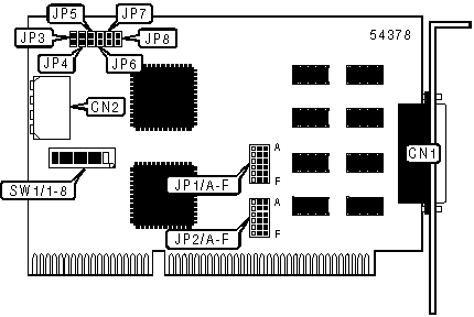
8 serial ports vis 25-pin connector |
CN1 |
DC power connector |
CN2 |
|
Note: Connector is used to supply voltage to peripheral devices through ports 3-8. Power may be supplied through 25-pin or 9-pin serial connectors. | |||
|
PORT 1 MODE SELECTION | ||||||
|
Mode |
JP1/A |
JP1/B |
JP1/C |
JP1/D |
JP1/E |
JP1/F |
|
RS-232 |
Pins 2 & 3 |
Pins 2 & 3 |
Pins 2 & 3 |
Pins 2 & 3 |
Pins 2 & 3 |
Pins 2 & 3 |
|
RS-485 |
Pins 1 & 2 |
Pins 1 & 2 |
Pins 1 & 2 |
Pins 1 & 2 |
Pins 1 & 2 |
Pins 1 & 2 |
|
Note: Pins designated are in the closed position. RJ-485 ports must also be software configured. | ||||||
|
PORT 2 MODE SELECTION | ||||||
|
Mode |
JP2/A |
JP2/B |
JP2/C |
JP2/D |
JP2/E |
JP2/F |
|
RS-232 |
Pins 2 & 3 |
Pins 2 & 3 |
Pins 2 & 3 |
Pins 2 & 3 |
Pins 2 & 3 |
Pins 2 & 3 |
|
RS-485 |
Pins 1 & 2 |
Pins 1 & 2 |
Pins 1 & 2 |
Pins 1 & 2 |
Pins 1 & 2 |
Pins 1 & 2 |
|
Note: Pins designated are in the closed position. RJ-485 ports must also be software configured. | ||||||
|
PORT 3 POWER | ||
|
Setting |
JP3 | |
| » |
Disabled |
Open |
|
+5V |
Closed | |
|
Note: Port is equipped with a fuse to break the circuit if the device draws more than .5 amp. | ||
|
PORT 4 POWER | ||
|
Setting |
JP4 | |
| » |
Disabled |
Open |
|
+5V |
Closed | |
|
Note: Port is equipped with a fuse to break the circuit if the device draws more than .5 amp. | ||
|
PORT 5 POWER | ||
|
Setting |
JP5 | |
| » |
Disabled |
Open |
|
+5V |
Closed | |
|
Note: Port is equipped with a fuse to break the circuit if the device draws more than .5 amp. | ||
|
PORT 6 POWER | ||
|
Setting |
JP6 | |
| » |
Disabled |
Open |
|
+5V |
Closed | |
|
Note: Port is equipped with a fuse to break the circuit if the device draws more than .5 amp. | ||
|
PORT 7 POWER | ||
|
Setting |
JP7 | |
| » |
Disabled |
Open |
|
+5V |
Closed | |
|
Note: Port is equipped with a fuse to break the circuit if the device draws more than .5 amp. | ||
|
PORT 8 POWER | ||
|
Setting |
JP8 | |
| » |
Disabled |
Open |
|
+5V |
Closed | |
|
Note: Port is equipped with a fuse to break the circuit if the device draws more than .5 amp. | ||
|
BOARD 1 ADDRESS SELECTION | |||||||||
|
Setting |
SW1/1 |
SW1/2 |
SW1/3 |
SW1/4 |
SW1/5 |
SW1/6 |
SW1/7 |
SW1/8 | |
|
100h |
Off |
On |
Off |
On |
On |
On |
On |
On | |
|
140h |
On |
Off |
Off |
On |
On |
On |
On |
On | |
| » |
180h |
Off |
Off |
Off |
On |
On |
On |
On |
On |
|
200h |
Off |
On |
On |
Off |
On |
On |
On |
On | |
|
240h |
On |
Off |
On |
Off |
On |
On |
On |
On | |
|
280h |
Off |
Off |
On |
Off |
On |
On |
On |
On | |
|
300h |
Off |
On |
Off |
Off |
On |
On |
On |
On | |
|
340h |
On |
Off |
Off |
Off |
On |
On |
On |
On | |
|
380h |
Off |
Off |
Off |
Off |
On |
On |
On |
On | |
|
Note: Board one switch settings determines other controller settings. A different address should be selected for each board. | |||||||||
|
BOARD 2 ADDRESS SELECTION | ||||||||
|
Setting |
SW1/1 |
SW1/2 |
SW1/3 |
SW1/4 |
SW1/5 |
SW1/6 |
SW1/7 |
SW1/8 |
|
100h |
Off |
On |
Off |
On |
On |
On |
On |
On |
|
140h |
On |
Off |
Off |
On |
On |
On |
On |
On |
|
180h |
Off |
Off |
Off |
On |
On |
On |
On |
On |
|
200h |
Off |
On |
On |
Off |
On |
On |
On |
On |
|
240h |
On |
Off |
On |
Off |
On |
On |
On |
On |
|
280h |
Off |
Off |
On |
Off |
On |
On |
On |
On |
|
300h |
Off |
On |
Off |
Off |
On |
On |
On |
On |
|
340h |
On |
Off |
Off |
Off |
On |
On |
On |
On |
|
380h |
Off |
Off |
Off |
Off |
On |
On |
On |
On |
|
BOARD 3 ADDRESS SELECTION | ||||||||
|
Setting |
SW1/1 |
SW1/2 |
SW1/3 |
SW1/4 |
SW1/5 |
SW1/6 |
SW1/7 |
SW1/8 |
|
100h |
Off |
On |
Off |
On |
On |
On |
On |
On |
|
140h |
On |
Off |
Off |
On |
On |
On |
On |
On |
|
180h |
Off |
Off |
Off |
On |
On |
On |
On |
On |
|
200h |
Off |
On |
On |
Off |
On |
On |
On |
On |
|
240h |
On |
Off |
On |
Off |
On |
On |
On |
On |
|
280h |
Off |
Off |
On |
Off |
On |
On |
On |
On |
|
300h |
Off |
On |
Off |
Off |
On |
On |
On |
On |
|
340h |
On |
Off |
Off |
Off |
On |
On |
On |
On |
|
380h |
Off |
Off |
Off |
Off |
On |
On |
On |
On |
|
BOARD 4 ADDRESS SELECTION | ||||||||
|
Setting |
SW1/1 |
SW1/2 |
SW1/3 |
SW1/4 |
SW1/5 |
SW1/6 |
SW1/7 |
SW1/8 |
|
100h |
Off |
On |
Off |
On |
On |
On |
On |
On |
|
140h |
On |
Off |
Off |
On |
On |
On |
On |
On |
|
180h |
Off |
Off |
Off |
On |
On |
On |
On |
On |
|
200h |
Off |
On |
On |
Off |
On |
On |
On |
On |
|
240h |
On |
Off |
On |
Off |
On |
On |
On |
On |
|
280h |
Off |
Off |
On |
Off |
On |
On |
On |
On |
|
300h |
Off |
On |
Off |
Off |
On |
On |
On |
On |
|
340h |
On |
Off |
Off |
Off |
On |
On |
On |
On |
|
380h |
Off |
Off |
Off |
Off |
On |
On |
On |
On |