DIAMOND FLOWER, INC.
MIO-400KF REV G+
|
Card Type |
Multi-I/O card |
|
Chip Set |
Unidentified |
|
Maximum Onboard Memory |
Unidentified |
|
I/O Options |
Floppy drive interface, game port, IDE interface, SCSI connector, parallel port, serial ports (2 RS-232) |
|
Hard Drives supported |
Two IDE (AT) drives |
|
Floppy drives supported |
Two 360KB or 720KB drives |
|
Data Bus |
16-bit ISA |
|
Card Size |
Half-length |
|
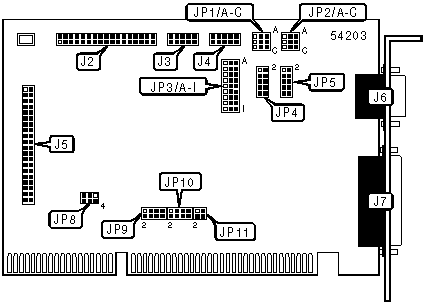
CONNECTIONS | |||
|
Function |
Label |
Function |
Label |
|
34-pin cable connector - floppy drive |
J2 |
IDE interface |
J5 |
|
Game port |
J3 |
9-pin serial port 1 |
J6 |
|
10-pin serial port 2 - internal |
J4 |
25 pin parallel port |
J7 |
|
USER CONFIGURABLE SETTINGS | |||
|
Function |
Label |
Position | |
| » |
Factory configured - do not alter |
JP3/H |
Unidentified |
| » |
Game port enabled |
JP3/I |
Pins 2 & 3 closed |
|
Game port disabled |
JP3/I |
Pins 1 & 2 closed | |
|
FLOPPY DISK CONTROLLER CONFIGURATION | ||
|
Function |
JP3/F |
JP3/G |
|
Floppy disk controller enabled |
Pins 2 & 3 closed |
Pins 2 & 3 closed |
|
Floppy disk controller disabled |
Pins 1 & 2 closed |
Pins 2 & 3 closed |
|
PORT 1 DATA CARRIER DETECT SETTING | ||
|
Setting |
JP1/A | |
| » |
DCD Normal |
Pins 1 & 2 closed |
|
DCD Forced true |
Pins 2 & 3 closed | |
|
PORT 2 DATA CARRIER DETECT SETTING | ||
|
Setting |
JP2/A | |
| » |
DCD Normal |
Pins 1 & 2 closed |
|
DCD Forced true |
Pins 2 & 3 closed | |
|
PORT 1 DATA SET READY SETTING | ||
|
Setting |
JP1/B | |
| » |
DSR Normal |
Pins 1 & 2 closed |
|
DSR Forced true |
Pins 2 & 3 closed | |
|
PORT 2 DATA SET READY SETTING | ||
|
Setting |
JP2/B | |
| » |
DSR Normal |
Pins 1 & 2 closed |
|
DSR Forced true |
Pins 2 & 3 closed | |
|
PORT 1 CLEAR TO SEND SETTING | ||
|
Setting |
JP1/C | |
| » |
CTS Normal |
Pins 1 & 2 closed |
|
CTS Forced true |
Pins 2 & 3 closed | |
|
PORT 2 CLEAR TO SEND SETTING | ||
|
Setting |
JP2/C | |
| » |
CTS Normal |
Pins 1 & 2 closed |
|
CTS Forced true |
Pins 2 & 3 closed | |
|
PORT 1 DTE/DCE SELECTIONTION | |
|
Setting |
JP5 |
|
DTE |
Pins 1 & 2. 3 & 4, 5 & 6, 7 & 8, 9 & 10 closed |
|
DCE |
Pins 1 & 3, 2 & 4, 5 & 7, 6 & 8, 9 & 10 closed |
|
PORT 2 DTE/DCE SELECTIONTION | |
|
Setting |
JP4 |
|
DTE |
Pins 1 & 2. 3 & 4, 5 & 6, 7 & 8, 9 & 10 closed |
|
DCE |
Pins 1 & 3, 2 & 4, 5 & 7, 6 & 8, 9 & 10 closed |
|
PARALLEL PORT ADDRESS SELECTION | ||
|
Setting |
JP3/A |
JP3/B |
|
LPT1 (3BCh) |
Pins 1 & 2 closed |
Pins 2 & 3 closed |
|
LPT2 (378h) |
Pins 2 & 3 closed |
Pins 2 & 3 closed |
|
LPT3 (287h) |
Pins 2 & 3 closed |
Pins 1 & 2 closed |
|
Disabled |
Pins 1 & 2 closed |
Pins 1 & 2 closed |
|
SERIAL PORT ADDRESS SELECTION | |||||
|
Port 1 |
Port 2 |
JP3/C |
JP3/D |
JP3/E |
JP8 |
|
COM1 (3F8h) |
COM2 (2F8h) |
Pins 2 & 3 |
Pins 2 & 3 |
Pins 2 & 3 |
Pins 1 & 2, 4 & 5 |
|
COM2 (2F8h) |
COM3 (3E8h) |
Pins 2 & 3 |
Pins 2 & 3 |
Pins 1 & 2 |
Pins 2 & 3, 5 & 6 |
|
COM1 (3F8h) |
COM4 (2E8h) |
Pins 2 & 3 |
Pins 2 & 3 |
Pins 2 & 3 |
Pins 1 & 2, 5 & 6 |
|
COM3 (3E8h) |
COM4 (2E8h) |
Pins 2 & 3 |
Pins 2 & 3 |
Pins 2 & 3 |
Pins 2 & 3, 4 & 5 |
|
COM1 (3F8h) |
Disabled |
Pins 2 & 3 |
Pins 1 & 2 |
Pins 2 & 3 |
Pins 1 & 2, 4 & 5 |
|
Disabled |
COM2 (2F8h) |
Pins 1 & 2 |
Pins 2 & 3 |
Pins 2 & 3 |
Pins 1 & 2, 4 & 5 |
|
Disabled |
Disabled |
Pins 1 & 2 |
Pins 1 & 2 |
Pins 1 & 2 |
Pins 1 & 2, 4 & 5 |
|
Note: Pins designated are in the closed position. | |||||
|
COM 1 & COM 3 INTERRUPT SELECTION | ||
|
IRQ |
JP10 | |
|
IRQ2 |
Pins 1 & 2 closed | |
|
IRQ3 |
Pins 7 & 8 closed | |
| » |
IRQ4 |
Pins 5 & 6 closed |
|
IRQ5 |
Pins 3 & 4 closed | |
|
COM 2 & COM 4 INTERRUPT SELECTION | ||
|
IRQ |
JP9 | |
|
IRQ2 |
Pins 1 & 2 closed | |
| » |
IRQ3 |
Pins 7 & 8 closed |
|
IRQ4 |
Pins 5 & 6 closed | |
|
IRQ5 |
Pins 3 & 4 closed | |
|
PARALLEL PORT INTERRUPT SELECTION | ||
|
IRQ |
JP11 | |
|
IRQ5 |
Pins 1 & 2 closed | |
| » |
IRQ7 |
Pins 3 & 4 closed |